MIMO Wireless Communications: From Real-World Propagation to Space-Time Code Design

In this appendix, the antenna coupling model presented in Section 2.6.2 is rigorously derived. We explain why the coupling matrix may only be derived if the antennas are minimum scatterers. We distinguish the cases of antennas being minimum scatterers with regard to impedance parameters, and minimum scatterers with regard to admittance parameters.
As explained in [RP94], antennas that are minimum scatterers with regard to impedance parameters are such that an open-circuited antenna behaves almost exactly as if it were not present at all. A typical example of such an antenna is the half-wave length dipole. Indeed, open-circuited half-wave length dipole elements become quarter-wave length wires, which have very small scattering cross sections [Han98].
The use of such antennas implies the following simplifications:
for receive antennas, the open circuit voltages do not depend on the presence of other elements.
the self impedances do not depend on the presence of other open-circuited antennas.
the element pattern in an open-circuited environment is identical to the isolated element pattern.
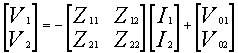
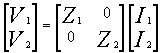
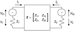
Consider two coupled antennas modeled as a two-port network. Each antenna is excited by a source represented by a Thevenin equivalent source with two series impedances Z 1 and Z 2. Denoting the currents at the antenna ports as I 1 and I 2 (see Figure D.1), we express [GK83] the voltages on the terminations, V 1 and V 2, as
| (D.1) | |
| (D.2) | |