CNC Programming Techniques: An Insider’s Guide to Effective Methods and Applications

Machining corners between two major elements of a contour is called corner-breaking. Breaking sharp corners between two elements of a contour typically applies to a 90 corner between a face (shoulder) and a diameter, or between a diameter and a face. There are two general categories:
Defined corners
Undefined corners
Into the first category belong chamfers and radiuses that have been defined in the drawing. For example, a chamfer may be defined as 1 45 mm, or a fillet radius as R0.5 mm. The second category covers all sharp corners that have to be broken, without actually specifying the size. Drawings often identify such breaks with a comment Break all sharp corners unless otherwise specified . Undefined corners need a specific size in the part program, and the CNC programmer has to make that decision. Typically, such corners are programmed as minimum breaks , usually in the 0.05 0.25 mm range (0.002 0.01 inches). Although such breaks often appear to be only cosmetic in nature, they still may have a practical application, such ease of handling, ease of assembly or both.
Regardless of their actual definition or purpose, corner breaks can be automated, providing certain conditions are present. Fanuc control systems offer a special programming feature called Automatic Corner Breaking for 90 corners.

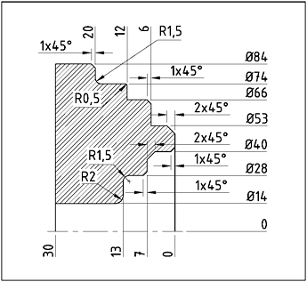
The illustration shows a typical application of a part that will benefit from the automatic corner breaking feature. Variety of chamfers and radiuses that have been used on external and internal contour may seem a bit...