Control of Continuous Linear Systems

2.5: Block Diagrams

2.5 Block Diagrams

Problem 2.25

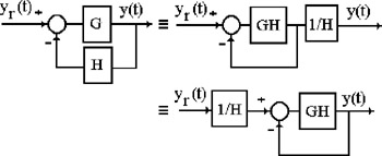
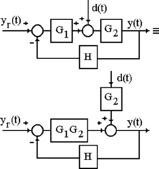
Show that the systems depicted in Figure 2.9, and in Figure 2.10, are equivalent (we have left out the argument s in the transfer functions of the various blocks).


Figure 2.9: Equivalent systems

Figure 2.10: Equivalent systems: Disturbed case
Solution 2.25

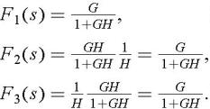
Recall that two systems are equivalent if their transfer functions are equal. The transfer functions of the systems depicted in Figure 2.9 are:


These three systems are equivalent.

For the first system depicted in Figure 2.10, we have:


For the second system, we obtain:


which leads to the same expression as before. Consequently, these two systems are equivalent.

Problem 2.26
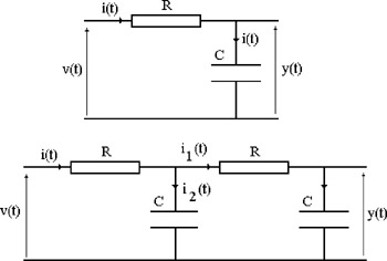
  1. Calculate the transfer function G ( s) of the RC system depicted at the top of Figure 2.11.


    Figure 2.11: RC systems

  2. Explain why the transfer function of the two RC systems depicted at the bottom of Figure 2.11 is not equal to the product G ( s) G ( s).

  3. Show that the RC system is equivalent to a closed-loop system with:


Solution 2.26
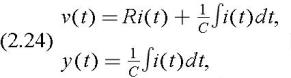
  1. From Ohm's law, we derive:


    where Ri( t) and 1/ C ? i( t) dt represent the voltage drops across the resistor and capacitor, respectively. Equation (2.24) expresses the fact that the input voltage v ( t) is the sum of the voltage drops across the resistor and capacitor. Taking the Laplace transform,


    we derive:


    This simple system is commonly used as a...

UNLIMITED FREE
ACCESS
TO THE WORLD'S BEST IDEAS

SUBMIT
Already a GlobalSpec user? Log in.

This is embarrasing...

An error occurred while processing the form. Please try again in a few minutes.

Customize Your GlobalSpec Experience

Category: IC Electronic Filters
Finish!
Privacy Policy

This is embarrasing...

An error occurred while processing the form. Please try again in a few minutes.