Dielectric Resonators, Second Edition
With renewed interest in dielectric resonator technology for modern wireless communications equipment, this book is an excellent reference for its understanding and application.
Pierre Guillon
In the past four decades, tremendous advances have been made in microwave filter technology. There are filter types for almost every usage that can be realized in waveguide and in microstrip technology. Dielectric resonators hold the promise of further enrichment of microwave filter designs. In fact, dielectric resonator filters have also been designed and used in radio systems as low as 1 GHz. In this chapter, the filter design principles, practical design considerations, and examples of dielectric resonator filters are presented.
The procedure for filter design is described as follows. Usually, we have to realize a microwave filter for which we know the type, the bandwidth, and the center frequency. Following the well established design principles, the external Q e (which defines the input and output coupling) and the coupling coefficient, k j,j+1, between two adjacent resonators are computed according to the filter specifications. To relate these values to the physical dimensions of the microwave dielectric filter, we have to compare these theoretical values of Q e and k j,j+1 to those obtained earlier in Ch. 8.
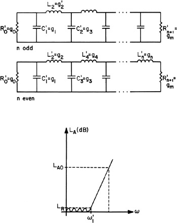
First, we will briefly review the filter design procedure such as described in [1]. Consider a typical low-pass prototype filter shown in Fig. 9.1 having a Chebyshev response. The attenuation is given by
| (9.1) | 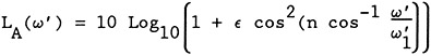 |
for ?' < ![]()
| (9.2) | 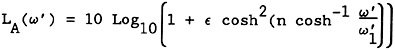 |
for ?' > ![]()
where
| (9.3) | |
| L Ar | = | pass-band ripple in dB |
| ?' | = |