Electrical Equipment Handbook: Troubleshooting and Maintenance

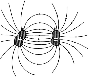
Figure 1.1 illustrates a capacitor. It consists of two insulated conductors a and b. They carry equal and opposite charges + q and ? q, respectively. All lines of force that originate on a terminate on b. The capacitor is characterized by the following parameters:
q,n the magnitude of the charge on each conductor
V, the potential difference between the conductors
The parameters q and V are proportional to each other in a capacitor, or q = CV, where C is the constant of proportionality. It is called the capacitance of the capacitor. The capacitance depends on the following parameters:
Shape of the conductors
Relative position of the conductors
Medium that separates the conductors
The unit of capacitance is the coulomb/volt (C/V) or farad (F). Thus
It is important to note that
but since
Thus,
This means that the current in a capacitor is proportional to the rate of change of the voltage with time.
In industry, the following submultiples of farad are used:
Microfarad (1 ?F = 10 ?6F
Picofarad (1 pF = 10 ?12F
Capacitors are very useful electric devices. They are used in the following applications:
To store energy in an electric field. The energy is stored between the conductors, which are normally called plates. The electric energy...