Network Analysis & Circuits

Chapter 12: Resonance and Selectivity

12.1 INTRODUCTION

A two-terminal network, in general, offers a complex impedance consisting of resistive and reactive components. If a sinusoidal voltage is applied to such a network, the current is then out of phase with the applied voltage. Under special circumstances, however, the impedance offered by the network is purely resistive. The phenomenon is called resonance and the frequency of the applied signal at that resonance is called the frequency of resonance or resonant frequency. The nature of resonance depends upon whether the inductance and the capacitance are in series or in parallel. Accordingly, we classify the resonant circuits into the following two categories:

(i) Series resonant circuit, and,

(ii) Parallel resonant circuit.

12.2 SERIES RESONANCE

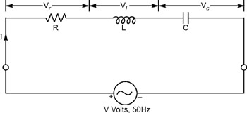
Figure 12.1 shows a series RLC circuit. A sinusoidal voltage V sends a current I through the circuit. The circuit is said to be resonant when the resultant reactance is zero, (i.e., the circuit is purely resistive or we can say the imaginary part should be equal to zero).


Figure 12.1: Series RLC circuit connected to a voltage source V

The impedance Z of the circuit is given by


where

Z and R in ohms

L is in Henrys

C is in Farads

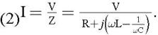
and is the angular frequency of the applied voltage in radians/sec. The current,


At resonance, the imaginary part of Z should be equal to zero


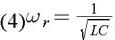
where ? 0 is the frequency of resonance in radians/seconds or the resonant frequency. From Equation (12.3), we get


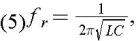
where f r is the...

UNLIMITED FREE
ACCESS
TO THE WORLD'S BEST IDEAS

SUBMIT
Already a GlobalSpec user? Log in.

This is embarrasing...

An error occurred while processing the form. Please try again in a few minutes.

Customize Your GlobalSpec Experience

Category: RF Inductors
Finish!
Privacy Policy

This is embarrasing...

An error occurred while processing the form. Please try again in a few minutes.