Oscillator Design and Computer Simulation, Second Edition
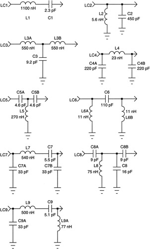
In the previous example a 3-element pi network was used for the cascade resonator. If the resonator is considered to be a simple filter it becomes apparent that a large variety of structures can serve as a resonator. In fact all lowpass, highpass and bandpass structures have the potential to serve as a resonator. Shown in Figure 2-5 are several such structures. The element values given assume a resonant frequency of approximately 100 MHz, a loaded Q of 6.9 and 50 ohm terminations.
LC1 and LC2 are basic series and parallel resonators. At resonance, the reactance of the series inductor and series capacitor cancel, and if the components are lossless, the network essentially vanishes. For equal source and load terminations maximum power transfer occurs. LC1 is capacitive below resonance and inductive above resonance. Both conditions impede signal transmission. Transmission phase shift is zero at resonance. The parallel resonator behaves in a dual fashion with maximum transmission and zero phase shift at resonance.
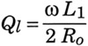
The loaded Q of the series resonator terminated at the source and load in R o is
| (2.11) | ![]() |
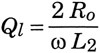
The loaded Q of the doubly-terminated parallel resonator is
| (2.12) | ![]() |
The difficulty with the simple series and parallel resonator is extreme element values with 50 ohm terminations as the loaded Q is increased. Notice in Figure 2-5 that...