Oscillator Design and Computer Simulation, Second Edition
An ideal oscillator output voltage is described mathematically as a pure sine wave of constant frequency and amplitude. A real oscillator output voltage is expressed as
| (4.1) | |
with random processes
| (4.2) | |
| (4.3) | |
In well-designed oscillators, amplitude noise is less significant than phase noise, and will not be considered further [1].
The phase noise performance of oscillators has become increasingly important because communications channels have become closer spaced and more heavily loaded, data transmission systems often require low phase noise, military EW and CCC systems are more sophisticated, and higher frequencies are being used by a variety of systems [2] . Broadband voltage-controlled oscillators used in electronically tuned PLL applications, which are now common, are inherently noisy.
Phase noise performance is described by various terms in both the frequency and time domains. In the frequency domain, the phase noise modulation creates continuous spectra sidebands, which generally decrease in level with increasing frequency offsets, f m, from the carrier. This common form of phase noise description is the single-sideband (SSB) phase noise, L( f m). The units are dBc/Hz, or decibels below the carrier in 1-Hz bandwidth.
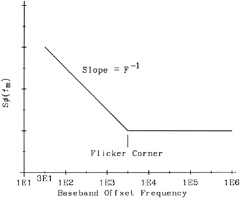
Before considering the phase noise of an oscillator, let us review the phase noise of an amplifier. Shown in Figure 4-1 is the asymptotic power spectral density S ?(fm) of the phase modulation term ?( t) for an amplifier. For large offsets [3]