Oscillator Design and Computer Simulation, Second Edition
2.8: Resonator Voltage

2.8 Resonator Voltage

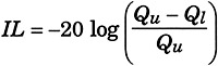
In an earlier section we listed desirable attributes of high loaded Q. However, there are fundamental limitations to the maximum loaded Q. As the cascade loaded Q approaches the unloaded Q of components in the resonator the resonator insertion loss approaches infinity. The insertion loss for the resonator is

(2.25)

where IL is a positive decibel number. IL is therefore equal to - S 21 dB. For example, if Q u = 100 and Q l = 21.5, IL = 2.1 dB. If the cascade amplifier has adequate gain then significant loss can be tolerated in the resonator. Nevertheless, the loaded Q can not exceed the component unloaded Q.

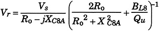
A second factor which may limit the maximum loaded Q is resonator voltage. This is particularly a problem with high-power oscillators and oscillators with varactor tuning elements. The voltage at resonance across the shunt inductor and capacitor in LC8, the top-C coupled parallel resonator, is given by

(2.26)

where V s is source voltage into R o ohms and B L8 is the admittance of the shunt inductor.

The insertion loss, Q l and V r versus X s are given in Figure 2-6 for Q u = 200, R o =50 ohms, V s = 0.707 V rms ( +10 dBm,) and B L8 = .01 mhos. Notice with only 0.707 volts drive...

UNLIMITED FREE
ACCESS
TO THE WORLD'S BEST IDEAS

SUBMIT
Already a GlobalSpec user? Log in.

This is embarrasing...

An error occurred while processing the form. Please try again in a few minutes.

Customize Your GlobalSpec Experience

Category: Q-switches
Finish!
Privacy Policy

This is embarrasing...

An error occurred while processing the form. Please try again in a few minutes.