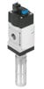
Pneumatic Drives: System Design, Modelling and Control

Directional control valves are primarily used to control the direction of flow between the components of a pneumatic circuit. Due to their internal resistance they also throttle the air flow, an effect that is usually not welcome. There are several ways to distinguish between directional control valves:
number of ports,
number of switching positions or internal stable states,
internal design, e.g. spool, poppet or diaphragm,
type of operation, e.g. electrical, pneumatical or manual.
Directional control valves are often characterised by two numbers: the number of main ports followed by the number of switching positions. The working ports are usually labelled 2 and 4, the exhaust ports 3 and 5 and the supply 1; the control ports of pneumatically operated valves are not counted. The valve in Fig. 12.2 has 5 ports and 2 distinct positions of the spool and is therefore called a 5/2-way directional control valve. Some typical valves and their symbols are shown in Table 12.1. The switching positions are represented by squares. Internal connections between ports for a given position are indicated by an arrow or arrows within the square. In circuit diagrams valves are always shown in the neutral position, i.e. valve not actuated.
| Symbol | Name / Description |
|---|---|
|
![]() | 2/2-way valve NC, direct electrically operated |
|
![]() | 3/2-way valve NC, electrically operated, with pilot valve |
|
![]() | 3/2-way valve NO, electrically operated |
|
![]() | 4/2-way valve, mechanically operated |
|
![]() | 5/2-way valve, electrically operated, monostable |
|
![]() | 5/2-way valve, electrically operated, bistable |
|
![]() | 5/3-way valve, pneumatically operated |
For 2/2-way...