Pneumatic Drives: System Design, Modelling and Control

Chapter 13: Shut-Off Valves

Overview

A shut-off valve is defined in ISO 5598 as a "valve whose main function is to prevent flow". Examples are non-return valves, shuttle valves or twin pressure valves.

In most circuits they can be treated as simple switches that work in binary mode: either completely open or completely closed. In critical applications the internal design has to be taken into account and leakage, over-or underlap and inertia have to be considered. An example is a non-return valve when the supply and load pressure are almost identical: a situation that can lead to severe oscillations, see Fig. 13.5. In these rare cases a very detailed mathematical model has to be built, using the equations from the first part of this book.

For digital simulations the inertia of the moving elements should be included. In most cases a simple first-order model is sufficient. This also provides a smooth transition of system variables which eases the burden for integration algorithms with variable step size.

13.1 Non-Return Valves

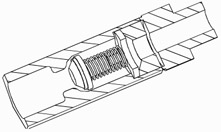
Non-return valves or check valves allow the flow of air in one direction almost unrestricted while blocking it in the opposite direction. As one manufacturer states, "free flow in one direction; fully leak-proof shut off in the other". A typical design is shown in Fig. 13.1, the symbol for a pneumatic circuit diagram in Fig. 13.2. In addition to balls other elements like cones, diaphragms or disks are used.


Figure 13.1: Cut-away view of a non-return valve, partially open

Figure 13.2: Symbol of a non-return...

UNLIMITED FREE
ACCESS
TO THE WORLD'S BEST IDEAS

SUBMIT
Already a GlobalSpec user? Log in.

This is embarrasing...

An error occurred while processing the form. Please try again in a few minutes.

Customize Your GlobalSpec Experience

Category: Industrial Valves
Finish!
Privacy Policy

This is embarrasing...

An error occurred while processing the form. Please try again in a few minutes.