Power Amplifier Design: A Collection from Applied Microwave & Wireless

With contributions from more than 20 experts, these articles present valuable resources for power amplifier linarization, measuring, modeling and distortion.
A thorough review of the techniques used in the fabrication of high power UHF/microwave bipolar RF power transistors
By Ted Johansson
From APPLIED MICROWAVE & WIRELESS, VOL. 11, NO. 3, SEPTEMBER/OCTOBER 1997
Whether you are an amplifier designer, applications engineer, technical manager or are just generally interested, RF power transistors often appear to contain quite a lot of magic and can require even more magic to use! This is partially true if we define magic as something not easily calculated, or in these days, simulated on a computer. This article describes some of the chip level design considerations and technical details for Eriesson s bipolar, high-voltage, high-power RF transistors.
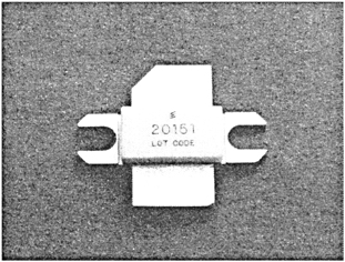
Figure 1 shows a typical Ericsson components RF power transistor for cellular radio output amplifiers. The transistor s outer dimensions are 24.3 mm 17.8 mm (0.96 in. 0.70 in). It can deliver 45 watts of output power at 1.8 to 2 GHz for PCN/PCS systems.
Bipolar RF power transistors are among the oldest silicon devices. High-frequency transistors first were fabricated in germanium in the late 1950s but soon were replaced by silicon bipolar transistors in the beginning of the 1960s and since then have dominated the RF-power area. In 1971, H.F.Cooke described the theory and design of these transistors in an often-cited paper [1]. Much of his text still is applicable to today s devices. Bipolar transistors dominate cellular radio...