Power Amplifier Design: A Collection from Applied Microwave & Wireless

With contributions from more than 20 experts, these articles present valuable resources for power amplifier linarization, measuring, modeling and distortion.
This design uses low-cost power FETs that bridge the gap between typical power devices and specialized RF devices.
Richard Frey
From APPLIED MICROWAVE & WIRELESS, VOL. 10, NO. 3, APRIL 1998
Power amplifiers for 80 MHz have typically used expensive ceramic-metal packaged RF devices. The use of an inexpensive TO-247 packaged transistor with an innovative internal device connection provides the basis for the cost-effective design presented here. This article describes a 300 watt amplifier for 81.36 MHz using a push-pull pair of plastic packaged devices. The design techniques and construction practices are described in enough detail to permit duplication of the amplifier.
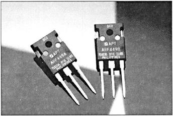
The devices used in the amplifier are the ARF449A and ARF449B symmetrical pair (see photo). These devices are targeted for high voltage, single frequency, class C operation. The operating voltage for the amplifier will be 125 volts. This was chosen as a compromise between the maximum available gain voltage and ruggedness when operating into high VSWR loads. These are a mirror-image connected pair of MOSFETs, each with the following characteristics:
BV dss=450 V
P d:= 165 W for T c=25 C
R ds(on)=0.72 ohm
C iss=980 pF
C oss=87 pF
C rss=25 pF
Because there are several different applications opportunities around 80 MHz, the second harmonic of the 40.68 MHz ISM frequency allocation was chosen as the operating frequency. The design goals for the amplifier are: