Practical MMIC Design
Filled with real-world design techniques and rules of thumb, this practical resource offers professionals a unique look into the day-to-day practices of MMIC production and the economics associated with it.
Circuits that switch RF and microwave signals are very useful, especially for applications such as phased-array radar and instrumentation. The best MMIC technology for switches is the FET because of the inherent isolation between the gate contact and the source and drain contacts, and because the gate draws virtually zero current in both control states (on and off) [128]. The advantages of MMIC FET switches over PIN diode switches [129] are that they have negligible dc power consumption and require much simpler bias and driver circuits.
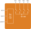
When used as a switch, the FET is in a passive mode (i.e., there is no dc bias voltage on the drain contact), and it functions as a voltage-controlled resistor. The basic topology is shown in Figure 5.132, where the resistance between the source and drain contacts is controlled by the voltage applied to the gate contact through a large value resistor (typically 4K ohms). This large resistor completely decouples the dc control circuitry from the RF signals and consumes negligible dc power because of the near-zero gate current. When zero bias is applied to the gate, the FET is in its low-impedance state, and when a negative voltage (greater than the pinch-off voltage, ~ -5volts) is applied to the gate, the FET is in its high-impedance state.
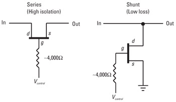
The simplest switch configuration is the single-pole single-throw (SPST) switch, which, as shown in Figure 5.132, can be formed from FETs in...