Practical MMIC Design

Filled with real-world design techniques and rules of thumb, this practical resource offers professionals a unique look into the day-to-day practices of MMIC production and the economics associated with it.
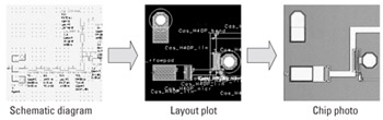
MMIC design requires that the circuit components be laid out on the planar surface of the semiconductor substrate, and this layout process is the mechanism of going from a schematic circuit design to the physical positioning of the many different layers that make up each component. For example, Figure 6.1 shows a portion of a schematic diagram in a CAD simulator and the associated layout plot displaying a number of the various layers, together with a photo of the resulting chip.
The physical position of all the features on a particular layer, which is stored in the layout CAD tool, is then used to write the photolithographic processing masks. These masks are then used in the wafer fabrication facility to form all of the features of the components physically on the substrate-wafer surface.
This chapter begins by describing the format of layout data files and the type of CAD tools that create them, then goes on to discus the typical process of laying out a chip design. The chapter continues by outlining the circuit arraying procedure, where multiple chip designs are formed into an array of circuits that is then stepped and repeated over the whole wafer surface, and concludes with some comments about mask manufacturing.
The physical features making up the components of an MMIC are either solid objects, such as a metal area or track, or holes in a continuous layer, such as the holes...