Protection of Electrical Networks
Suitable for engineers, technicians, designers and operators working with electrical networks, this book discusses network structures and grounding systems, as well as problems that can occur in networks.
 TABLE OF CONTENTS
 Fixed bank
The equivalent upstream network single-phase diagram during energization of the fixed bank is shown in Figure B-1.
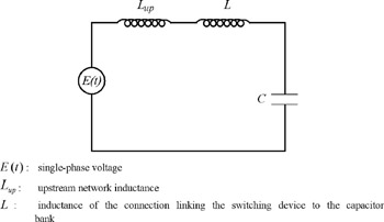
We shall demonstrate that the frequency of the transient current occurring upon energization is very high (see section 10.6.1, example 1; f 0 1,582 Hz).
This results in justification of neglect of the network resistance in relation to the inductance: R up ?2 ? f 0 L up, since f 0 ? 50 Hz.
Similarily, the resistance of the connection linking the switching device to the capacitor is negligible.
The network frequency (50 Hz) is negligible in relation to the transient current frequency. We might therefore consider that we have a voltage step throughout the duration of the transient current.
The value of the step, at worst, is the peak value of the sinusoidal voltage:

U n: phase-to-phase voltage
The current i( t) is determined by the following differential equation:

We shall solve this equation using Laplace transforms.
As a Laplace transform, the differential equation becomes:

The current is zero before energization and it is assumed that the voltage at the capacitor terminals is zero (worst case).
Hence: i( t=0) = 0 and V C ( t = 0) = 0 thus giving us: 

Let us take: 

Using the Laplace transform tables, we can deduce i( t):

The maximum peak inrush current is thus:

A and its frequency:

Switched...