4.11 ENGINEERING DWDM SYSTEMSEngineering a DWDM system begins with a market investigation to understand the business opportunities and how the "to be built" system fits the communications market and the business portfolio. There are two golden rules to be met (that market research experts know well) for the success of new product: the "to be built" system must differ from any other product on the market, and it must offer a measurable benefit to the customer that no other previous product offers; that is, it has found a niche in the communications equipment space offering a solution to a known problem. When these rules are met, a tedious iterative process begins that involves the interplay of cost/benefit modeling, engineering, and market interaction. When this interplay is fine-tuned, the design process begins. 4.11.1 Parameters That Influence Optical Design In this section, we do not address the market differentiator or the potential market opportunities present at different network layers, but we focus only on the engineering process that impacts the design of a DWDM system and the quality of signal and service. First, however, we examine the key parameters that influence the design of a DWDM system and a network. These are: - system aggregate bandwidth capacity
- channel capacity per fiber
- operating band (C, L, etc.) and ITU-T nominal center frequencies (wavelengths)
- channel granularity; channel spacing or separation and channel width
- channel bit rate and modulation (% RZ, NRZ, soliton, etc.)
- multichannel frequency stabilization
- channel performance (BER limits)
- channel allowable dispersion (chromatic, polarization)
- signal polarization states and polarization strategies
- power launched in fiber
- power received (receiver sensitivity)
- system/network application (Metro, LH, small, large, access-type, etc.)
- OSNR level at the receiver
- differential group delay (DGD)
- performance management capability
- redundancy strategy (controller, optical cross-connect)
- I/O port protection scheme (1 + 1, 1:N, etc.)
- control architecture (hierarchical, other)
- interboard communications and communication protocol (100 GbE, 1 GbE, etc.)
- fault detector strategy (location and type of sensors for power, wavelength, polarization, etc.)
- fault/degradation management strategy (monitoring, detection, correlation, alarm, provisioning, isolation and recovery)
- supervisory channels strategy and protocols
- optical amplification strategy (SOA, FOA, RAMAN, hybrid)
- number of fiber spans
- length of span between amplifiers
- fiber type(s) used as the transmission medium
- worst-case optical power budget per path
- optical loss and power budget across system I/Os
- aggregate bandwidth management
- supported transport services (synchronous, asynchronous, multiservices)
- signal format (SONET, ATM, IP, digital wrapper)
- communications standards compliance
- connectivity with network management system and communications protocols (TL1, etc.)
- configuration strategy (remote, local, manual)
- system protection and survivability strategies
- service protection plan for uninterrupted service offering
- system scalability and flexibility (non-service-affecting)
- system provisioning and upgrades (connectivity tables, laser parameters, configuration, etc.), remote and local (CIT)
- wavelength management (wavelength converters)
- physical size, physical partitioning of functions and system collocation.
- physical and environmental standards compliance (NEBS, ETSI, etc.)
- powering plant (power feeders, converters, indicators, fuses, voltages, etc.)
- cabling plant
- smart connectorization for protection (automatic laser shut-down upon disconnect, power-up upon contact)
- heat management
- system reliability
- system security
- visual indicators
- interoperability; compatibility with optical parameters, transmission and transport protocols, survivability strategy and management
- interdomain compatibility
4.11.2 ITU-T Recommended Frequencies ITU-T G.692 (as of October 1998 has recommended 81 channels (wavelengths) in the C-band starting from 1,528.77 nm and incrementing in multiples of 50 GHz (or 0.39 nm). According to this, the first center frequency is at 196.10 THz (or 1,528.77 nm), and decrementing by 50 GHz (or incrementing by 0.39 nm), all center frequencies (wavelengths) are calculated. Thus, the first of the 81 channels in the C-band is at frequency 196.10 GHz or wavelength 1,528.77 nm, the second channel is at frequency 196.05 GHz or wavelength 1,529.16 nm, and so on, and the last frequency is at 192.10 GHz or wavelength 1,560.61 nm. However, the reference frequency is 193.1 Thz. As DWDM technology evolves and a wider spectrum becomes usable, more channels are included. For channel spacing of 100 GHz, the center frequencies of the channels are those that start with the first channel in the table and continue every other one, and similarly, for channel spacing of 200 GHz or 400 GHz. 4.11.3 Channel Capacity, Width, and Spacing The number of channels, the channel selection (center frequency), and the frequency width of each channel, as well as the channel separation, are important parameters in DWDM system design. Channel separation should allow for a frequency deviation (~2 GHz) caused by frequency drifts in the laser, filter and amplifier devices and thus to avoid interchannel interference. 4.11.4 Channel Bit Rate and Modulation The bit rate of channel and the modulation technique are parameters that determine the limits of channel width and channel separation, as well as channel performance (e.g., BER, cross-talk, etc.). Dispersion and dispersion management as well as noise induced by amplifiers and by other sources should also be considered because they affect the signal-to-noise ratio and thus the signal integrity. In addition, the differential group delay has a limiting effect on the bit rate by means of the receiver sensitivity (Fig. 4.57). 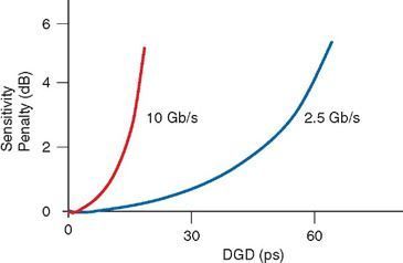 Figure 4.57 Impact of DGD on receiver for 2.5 and 10 Gb/s (put in engineering systems). 4.11.5 Multichannel Frequency Stabilization In DWDM systems with optical filters, filter detuning, or frequency offset from the center frequency, takes place. As detuning increases, interference with neighboring channels, optical cross talk, and insertion loss increase. 4.11.6 BER and Channel Performance The bit error rate (BER) is a performance metric specified in standards. DWDM systems should be designed such that the signal integrity is maintained at the expected levels. The BER depends on interchannel interference, optical power level at the receiver with respect to the sensitivity of the receiver, modulation technique, and other noise sources (externally coupled noise, jitter, nonlinear phenomena, etc.). 4.11.7 Channel Dispersion Fiber dispersion (chromatic and PMD) causes optical pulse widening. As dispersion increases, so does intersymbol interference and cross-talk (which affects signal integrity) and received power decreases (that impacts receiver sensitivity). 4.11.8 Power Launched The maximum allowable power per channel launched in the fiber, or the transmitted power, the receiver sensitivity, and the fiber loss between the two are the starting points for power calculations to ensure that the optical signal arrives at the receiver with enough power to be detected with an expected bit error rate objective (e.g., BER = 10–12). However, the maximum allowable power per channel cannot be arbitrary because of nonlinear phenomena and safety reasons. 4.11.9 Optical Amplification and Compensation Optical signal losses should be carefully budgeted, and optical amplification (SOA, OFA, Raman) should be used appropriately to restore the intensity of the optical signal (if needed). Concatenated optical amplification introduces cumulative ASE noise. Similarly, dispersion compensation may be required at high bit rates and long fiber spans. However, both amplifications and compensation introduce cumulative effects in ASE noise and in residual dispersion, as well as dispersion slope. 4.11.10 The Fiber-Medium and Limitations There are a number of limitations imposed on optical transmission by the fiber medium; linear and nonlinear effects such as fiber attenuation, chromatic dispersion, PMD, Kerr effect, FWM, SBS, and so on, that all contribute to degradation of optical signal and thus system performance. For a fixed length of fiber, the only variable that can be manipulated to lower the nonlinear contribution is the optical power. However, when lowering the optical power, the bit rate should be lowered to maintain transmission at the expected bit error rate. In general, the parameters specific to fibers are listed in Table 4.11. 4.11.11 Optical Power Budget Optical power budget of a path involves calculating all optical signal losses caused by every component in the optical path between transmitter and receiver (couplers, filters, cross-connects, connectors, splices, mux/demux, fiber, optical patch panels, etc.). It also involves power degradations due to linear and nonlinear effects resulting from the light-matter-light interaction, including noise sources. The main objective of the budget is to ensure that the power of the optical signal at the receiver is greater than the sensitivity of the receiver. 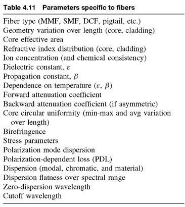 Power gain and loss (in dB) are additive, and thus the power budget reduces to straightforward addition or subtraction. Typically, the power of the optical signal to be launched into fiber is at 0 dB. Then, the dB loss of each lossy item in the path is subtracted from it, and the gain for optical amplifiers is added to it. In Chapter 1, we discussed the decibel unit and the precautions to be taken when adding or subtracting dBs and dBms. The net power is then compared with the receiver sensitivity. Typically, a net power margin of several dBs is desirable. (Margin) = (Transmitter output power) – (Receiver sensitivity) – (Σ losses , (dB) As an example, the total loss in a path is calculated by the sum 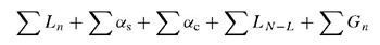 where Ln represents the loss of each fiber segment, αs is the mean splice loss, αc is the mean loss of line connectors, ΣLN–L is the sum of power degradations due to nonlinear effects, including noise sources (a rather involved sum), and ΣGn is the sum of gain. In short, for a given transmitter output power and receiver sensitivity, the power budget determines the path length between transmitter and signal regeneration, as well as the bit rate. For example, at OC-12 rate for transmitter output 0 dBm and receiver sensitivity –35 dBm, the fiber length (for SMF) is determined to be 64 km without amplification. Similarly, at OC-48 and receiver sensitivity of –29 dBm, the fiber length is determined to be 51 km; for fibers with improved transmission characteristics, these lengths are calculated longer. 4.11.12 Power Budget Calculations by Example In this section, we focus further on the optical power budget of the path, as this is a very critical engineering function for all-optical communications systems and networks. The optical power budget involves everything that is on the path of the optical signal: - optical connectivity (connectors, splices, patch panels)
- transmitter power and receiver sensitivity
- amplification strategy, the number of amplifiers in the path
- length of each span
- length of the path
- received quality of signal (expected BER and OSNR)
- number of channels and granularity, and more
- linearities and nonlinearities (dispersion, FWM, etc.)
- and many more
There are several factors that affect the signal power level due to loss along an optical path, some obvious and some rather hidden. One hidden source lies in fiber-to-fiber connectivity because of one or more mismatches: - connecting different fiber types
- fiber characteristics (polarization, birefringence, etc.) mismatch
- angular misalignment
- core diameter mismatch
- lateral offset
- numerical aperture mismatch
- concentricity mismatch
- core ellipticity mismatch
- excessive distance (gap) between fibers
- temperature variation along the fiber (part is underground and part is aerial)
Another hidden source of optical power loss is reflections at the end-face of a fiber, also known as Fresnel reflections. Reflections traveling toward the source may cause noise and thus increase the BER. Reflections are reduced by treating the fiber ends with AR coatings, angled finished faces, and ferrules with a small radius. The reflected optical power in a fiber is expressed as part of the reflection loss, or the reduction of reflected energy compared with transmitted energy. Treated fiber has a return loss in the range of –30 to –60 dB, and if the fiber face is angled finished –60 dB. Although component specifications vary from manufacturer to manufacturer, Table 4.12 lists the approximate loss values used in our examples (actual values should be consulted from manufacturers' specification data sheets). Example #1: Consider an optical module, the diagram of which is shown in Figure 4.58. Calculate the total input to output insertion loss (IL) if each monitoring device (Mon) subtracts 0.6 dB; consult Table 4.12 for connector losses. (Answer: 15.0 dB) 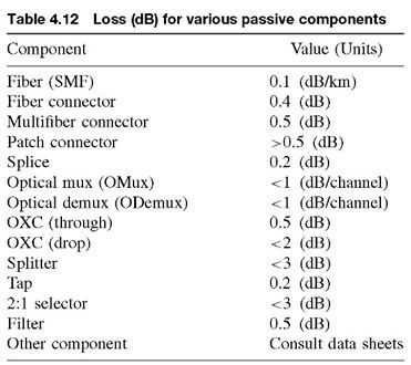
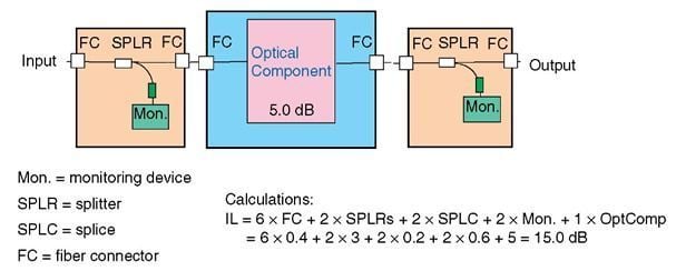
Figure 4.58 Example of IL calculations of an optical module. 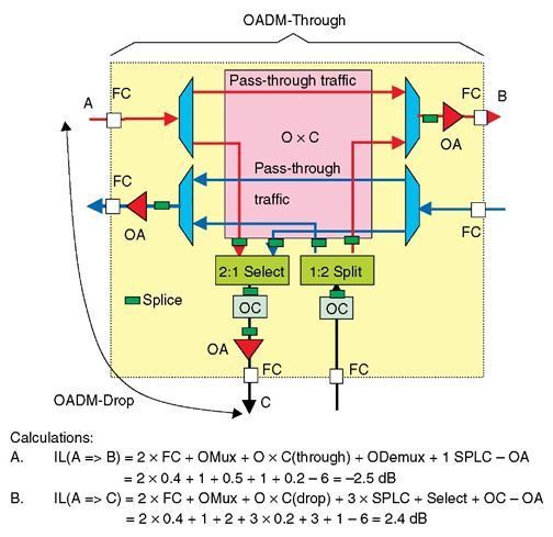 Figure 4.59 Example of IL calculations of an OADM. Example #2: Consider an OADM module, the diagram of which is shown in Figure 4.59. Calculate the IL per channel for - the OADM-through
- the OADM-drop side
The gain of the OA is 6 dB and for the wavelength converter (OC) is 1 dB. Consult Table 4.12 for connector losses. (Answer: a. –2.5 dB, b. 2.4 dB) Example #3: The optical output at a transmitter is 0 dB. The receiver sensitivity (for a given bit rate per channel and BER) is –40 dB. Calculate the maximum fiber span on the basis of loss only. (Answer: for 40 dB total loss and for a fiber with 0.1 dB/km,
the total span is 400 km) Example #4: For the example #3, and for 400 km span, if the fiber PMD coefficient is 0.2 ps/ , based on PMD calculations only and without PMD compensation, could the highest bit rate be 40 Gb/s? , based on PMD calculations only and without PMD compensation, could the highest bit rate be 40 Gb/s? (Answer: 0.15 x  = 4.0 ps; this corresponds to a bit rate » 40 Gb/s, = 4.0 ps; this corresponds to a bit rate » 40 Gb/s,
so the answer is yes) Example #5: For the example #4, considering both PMD and chromatic dispersion at 0.5 ps/nm-km, - What the highest maximum bit rate would be without compensation?
- How much compensation would be required to transmit at 40 Gb/s?
(Answer: a. 0.2 x + 0.5 x 400 = 204 ps; this corresponds to a bit rate 5 Gb/s;
b. 40 Gb/s has a period of 25 ps. The required compensation should be
such that 204 is reduced to 25 or less, thus 180 ps total) Example #6: For the example #5, considering a DCF with a coefficient of –100 ps/ nm-km and ignoring DCF fiber loss, how many kilometers of DCF should be used? (Answer: 180/100 = 1.8 km) Example #7: Single-mode power loss calculations for a DWDM optical link (the following is an approximate example of power loss calculations over an optical link and for 40 optical channels). Fiber used:
Fiber loss:
Chromatic Dispersion:
PMD:
Total fiber span length:
Number of OChs:
Channel separation:
Transmitter wavelength accuracy:
Transmitter output power, PT:
Bit rate:
Detector type:
Maximum receive signal/OCh:
Receiver power sensitivity, PR:
Opt. Mux/Demux through IL:
Opt. Mux/Demux drop IL:
Amplification gain:
Number of fiber connectors in path:
Number of fiber splices in path:
Number of expected future splices (margin):
Margin due to degradations: | Standard SMF
0.1 dB/km
0.5 ps/nm-km
0.12 ps/
80 km
40 in C-band
100 nm
f ± 20 nm
0 dB
10 Gbps
APD
–20 dBm
–33 dBm @ 10–9 BER
7 dB
8 dB
0 dB
4
10
4
2 dB |
Calculations: | 1. Transmitter output power: | | 0 dBm | | | 2. Receiver sensitivity (@10–9 BER): | PR | –33.0 dBm | | | 3. Total fiber system gain (#1-#2): | G | | 33 dB | | 4. Dispersion loss (@10–9 BER): | PD | 1.0 dB | | | Miscellaneous losses: | PMisc | 0.4 dB | | | 5. Connector losses (4@0.5 dB each): | LC | 2.0 dB | | | 6. Splice losses (10@0.2 dB each): | LS | 2.0 dB | | | 7. Margin for future 4 repair splices: | MR | 0.8 dB | | | 8. Margin for WDM upgrades: | MWDM | 3.0 dB | | | 9. Maximum allowable fiber loss: | L | | 23.8 dB | | (#3-#4-#5-#6-#7-#8-#9) | | | | | 10. Total loss due to fiber: | LF | 8.0 dB | | | 11. Margin due to degradations | PMargin | 2.0 dB | | 12. Received power level: | R | –33.8 dBm | | | (#1-#10-#11-#12) | | | |
Conclusions The received power level (–33.8 dBM) is within the receiver sensitivity (–35 dBm @ 10–9 BER), with only 1.2 dB additional margin left. Consequently, no pre-amplification or attenuation at the receiver is required. In addition, the total dispersion per channel is a little over 40 ps, and thus at 10 Gb/s (100 ps period), no dispersion compensation is required. However, if this fiber span is to be concatenated with more similar spans to construct a longer path, dispersion compensation of 60 to 80 ps will be required at least every other amplification stage (or every 160 km) and for 6 to 8 spans. Example #8: Calculate the fiber span from the optical power budget. Consider the following parameters: Transmitter launched power = Tx
N connectors each with IL = Lconn
K splices each with IL = Lsplice
Tap loss for monitoring = Lmon
Receiver sensitivity = Rxsens
Fiber Loss coefficient = α dB/km
Margin of 3 dB, or otherwise specified Then the maximum loss between transmitter and receiver is Max. loss = Lspan + NLconn + KLsplice + Lmon The maximum allowable loss is then Max. allowable loss = Max. loss + margin The fiber span loss Lspan is: Lspan = Tx – Rxsens – margin – NLconn – KLsplice – Lmon From this and the fiber loss coefficient α (dB/km), the fiber span is calculated: Fiber span = Lspan/α (km) Example #9: Channel capacity supported by linear optical fiber systems and networks Before fiber-optic systems were in use, Shannon developed a mathematical theory that related the channel capacity with the signal-to-noise (S/N) ratio. His celebrated relationship has been used extensively in all communications fields, electrical, optical, and wireless: Channel capacity = log2 (1 + S/N) Using a typical value of S/N = 40 dB, a channel capacity of 13 bits/s-Hz is obtained (notice that the logarithm is base-2). Although this number at first glance looks small, note that it is per Hertz; that is, the channel capacity 13 b/s is multiplied by a giganum-ber of 109 in a GHz system, and by 1012 in a THz system. Today, the highest commercially available bit rate of 40 Gb/s represents only a small fraction of b/s-Hz. Note, however, that the above relationship and theory consider a linear transmission medium. In reality, and particularly in DWDM systems, one must consider nonlinear optical fiber and related phenomena. Then the channel capacity is mathematically more involved because it requires solution of the nonlinear Shrödinger equation, signal and noise powers have a statistical distribution (such as Gaussian, Poisson, or other), nonlinear phenomena must be included (such as Kerr effect, polarization effects), photon-photon interactions (such as four-wave mixing, etc.), dispersion effects as well as the multispan fiber path. Then this case proves that Shannon's theoretical treatment provides the first order of magnitude solution to channel capacity, which in most applications is more than adequate because bit rates are not very high and there is not a high density of optical channels (access, Metro, short-haul), and it is applicable only to the very dense and ultrahigh bit rate systems and networks. Example #10: Number of optical channels supported in a fiber network - Determine the conditions that N optical channels in a WDM system over a bandwidth spectrum B(λ) expressed in nm. Consider that for a bit rate of B Gb/s, 2B GHz of bandwidth is needed for encoding (this determines the channel width) and that for low cross-talk, (as a rule of thumb), a channel spacing of 6B GHz is required.
For a center frequency λ, and from the identity
Δf = cΔλ/λ2
the bandwidth range (in terms of frequency) is:
Δf = B(f) = B(λ)c/λ2 Now, the bandwidth required over all N channels is:
Breq = 2BN + 6B(N – 1)
Assuming that Breqis equal to or less than B(f), then
N = (Breq + 6B)/8B Clearly, if Breq is greater than B(f), then the accommodated number of channels can be smaller.
- For the previous example, calculate the maximum number of channels that fit in Δf.
For a bandwidth Δf and for the same assumptions, the maximum number of channels is calculated by
N = (Δf + 6B)/8B -
For the previous example, consider that the channel spacing is fixed to CSand that the channel width to CW. How many channels can fit in bandwidth Δf?
From
Δf = (CW)N + CS(N – 1)
one obtains
N = (Δf + CS)/(CW + CS)
EXERCISES - The digital cross-connect executes a "call processing protocol" to establish input-output connectivity (5 points). True or False?
- A switch is a dynamic cross-connecting machine. An electronic switch is designed such that it can switch both synchronous and asynchronous traffic. True or False?
- A purely optical cross-connecting fabric is limited by the:
- type of traffic True or False?
- signal bit rate True or False?
- Explain what we mean by "remoting."
- A hybrid node has eight quad-OC-12 input-output units and a maximum cross-connect capacity = 50 Gb/s. We forecast an increase in bandwidth demand, and we would like to upgrade the node to handle 50% more input-output capacity, yet maintain a 15% margin of cross-connect capacity. What you would recommend:
- upgrade the input-output units
- Increase the switching bandwidth capacity
- Both
- Do nothing
- Consider the optical node of problem 5. It consists of four shelves; two shelves are allocated for the eight input-output units, controllers, and a timing unit; one shelf for the cross-connecting fabric, drivers, and controller; and the fourth shelf for power feed, craft access, alarm display, and test units. What type of controller would you recommend (simplex or duplex) for each shelf?
- The 1 + 1 protection requires two identical but separate paths that connect the two end-terminals; each end-terminal feeds the same traffic in the two separate fiber paths. True or False?
- Backbone systems are mostly applicable in networks that connect nodes separated by a maximum of 100 km. True or False?
REFERENCES - S.V. Kartalopoulos, Introduction to DWDM Technology: Data in a Rainbow, IEEE Press, New York, 2000.
- S.V. Kartalopoulos, Understanding SONET/SDH and ATM: Communications Networks for the Next Millennium, IEEE Press, New York, 1999.
- J.C. Palais, Fiber Optic Communications, 3rd ed., Englewood Cliffs, NJ., Prentice-Hall, 1992.
- B. Furht, Handbook of Internet and Multimedia: Systems and Applications, IEEE Press, New York, 1999.
- L.G. Raman, Fundamentals of Telecommunications Network Management, IEEE Press, New York, 1999.
- I.P. Kaminow and T.L. Koch, eds., Optical Fiber Communications IIIA and Optical Fiber Communications IIIB, Academic Press, 1997.
- R.A. Linke, Optical heterodyne communications systems, IEEE Comm. Mag., Oct. 1989, pp. 36-41.
- R.A. Linke and A.H. Gnauck, High-capacity coherent lightwave systems, J. Lightwave Tech-nol., vol. 6, no. 11, 1988, pp. 1750-1769.
- R.E. Slusher and B. Yurke, Squeezed light for coherent communications, J. Lightwave Tech-nol., vol. 8, no. 3, 1990, pp. 466-477.
- T. Wildi, Units and Conversion Charts, IEEE Press, New York, 1991.
- J. Nellist, Understanding Telecommunications and Lightwave Systems, IEEE Press, New York, 1996.
- A. Borella, G. Cancellieri, and F. Chiaraluce, Wavelength Division Multiple Access Optical Networks, Artec House, Boston, 1998.
- B.T. Doshi, S. Dravida, P. Harshavardhana, O. Hauser, and Y. Wang, Optical network design and restoration, Bell Labs Tech. J., vol. 4, no. 1, 1999, pp. 58-84.
- S. Chatterjee and S. Pawlowski, All-optical networks, Comm. of the ACM, vol. 47, no. 6, June 1999, pp. 74-83.
- S.V. Kartalopoulos, A Manhattan Fiber Distributed Data Interface Architecture, Globe-com'90, San Diego (December 2-5, 1990).
- S.V. Kartalopoulos, Disaster Avoidance in the Manhattan Fiber Distributed Data Interface Network, Globecom'93, Houston, TX, December 2, 1993.
- Y. Chen, M.T. Fatehi, H.J. LaRoche, J.Z. Larsen, and B.L. Nelson, Metro optical networking, Bell Labs Tech. J., vol. 4, no. 1, 1999, pp. 163-186.
- D.B. Buchholz et al., Broadband fiber access: A fiber-to-the-customer access architecture, Bell Labs Tech. J., vol. 4, no. 1, 1999, pp. 282-299.
- G.C. Wilson et al., FiberVista: An FTTH or FTTC System Delivering Broadband Data and CATV Services, Bell Labs Tech. J., vol. 4, no. 1, 1999, pp. 300-322.
- M. Berger et al., Pan-European optical networking using wavelength division multiplexing, IEEE Comm. Mag., vol. 35, no. 4, 1997, pp. 82-88.
- D. Cotter, J.K. Lcek, and D.D. Marcenac, Ultra-high-bit-rate networking: From the transcontinental backbone to the desktop, IEEE Comm. Mag., vol. 35, no. 4, 1997, pp. 90-96.
- E. Traupman, P. O'Connell, G. Minnis, M. Jadoul, and H. Mario, The evolution of the existing infrastructure, IEEE Comm. Mag., vol. 37, no. 6, 1999, pp. 134-139.
- A.G. Malis, Reconstructing transmission networks using ATM and DWDM, IEEE Comm. Mag., vol. 37, no. 6, 1999, pp. 140-145.
- H. Toba and K. Nosu, Optical frequency division multiplexing systems: Review of key technologies and applications, IEICE Trans. Commun., vol. E75, no. 4, Apr. 1992, pp. 243-255.
- O.E. DeLange, Wide-band optical communication systems: Part II-frequency-division-multiplexing, Proc. IEEE, vol. 58, no. 10, 1970, pp. 1683-1690.
- D.K. Hunter et al., WASPNET: A wavelength switched packet network, IEEE Comm. Mag., vol. 37, no. 3, March 1999, pp. 120-129.
- A. Asthana et al., Towards a Gigabit IP Router, J. High-Speed Networks, vol. 1, no. 4, 1992.
- M.A. Marsan, A. Bianco, E. Leonardi, A. Morabito, and F. Neri, All-Optical WDM Multi-Rings with Differentiated QoS, IEEE Communications Magazine, vol 37, no 2, Feb. 1999, pp. 58-66.
- M.A. Marsan et al., Daisy: a Scalable All-Optical Packet Network with Multi-Fiber Ring Topology, Computer Networks and ISDN Systems, vol. 30, 1998, pp. 1065-82.
- I. Gidon and Y. Ofek, MetaRing – a full-duplex ring with fairness and spatial reuse, IEEE Trans. Communications, vol. 41, no. 1, Jan. 1993, pp. 110-20.
- J.M. Simmons et al., Optical crossconnects of reduced complexity for WDM networks with bidirectional symmetry, IEEE Photonics Technology Letters, vol. 10, no. 6, June 1998, pp. 819-821.
- E.A. De Souza et al., Wavelength-division multiplexing with femtosecond pulses, Optics Letters, vol. 20, no. 10, 1995, pp. 1166-1168.
- E. Modiano, WDM-based packet network, IEEE Comm. Magazine, vol. 37, no. 3, March 1999, pp. 130-135.
- R. Glance, K. Pollock, C.A. Burrus, B.L. Kasper, G. Eisenstein, and L.W. Stulz, Densely spaced WDM coherent optical star network, Electron. Lett., vol. 23, no. 17, 1987, pp. 875-876.
- N. Takato et al., 128-channel polarization-insensitive frequency-selection-switch using high-silica waveguides on Si, IEEE Photon. Technol. Lett., vol. 2, no. 6, 1990, pp. 441-443.
- Y.-K.M. Lin, D. Spears, and M. Yin, Fiber-based local access network architectures, IEEE Comm. Mag., Oct. 1989, pp. 64-73.
- A. McGuire, Architectural Models for Supervisory and Maintenance Aspects of Optical Transport Networks, ICC '97 Workshop on WDM Network Management and Control, Montreal, Quebec Canada (8 June 1997).
- E. Goldstein, The Case for Opaque Multiwavelength Lightwave Networks, ICC'97 Workshop on WDM Network Management and Control, Montreal, Quebec Canada (8 June 1997).
- M. Garnot et al., Dimensioning and optimization of the wavelength-division-multiplexed optical layer of future transport networks, Proceedings IEEE ICC'98, Atlanta, Georgia, June 7-11, 1998, pp. 202-206.
- P. Black and T. Meng, A 1-Gb/s four-state sliding block Viterbi decoder, IEEE JSSC, vol. 32, no. 6, June 1997, pp. 797-805.
- D. Edforrs et al., An introduction to orthogonal frequency-division multiplexing,http://www.tde.lth.se/home/oes/publications.html.
- S.V. Kartalopoulos, An associative RAM-based CAM and its application to broad-band communications systems, IEEE Trans. Neural Networks, vol. 9, no. 5, 1998, pp. 1036-1041.
- S.V. Kartalopoulos, Ultra-fast pattern recognition in broadband communications systems, ISPACS'98 Conference Proceedings, Melbourne, Australia, November 1998.
- R.E. Matick, Transmission Lines for Digital and Communication Networks, IEEE Press, New York, 1995.
- Members of the Technical Staff, Transmission Systems for Communications, Bell Telephone Laboratories, New York, 1982.
- S.U.H. Qureshi, Adaptive equalization, Proc. IEEE, vol. 73, no. 9, Sept. 1985, pp. 1349-1386.
- S.V. Kartalopoulos, All fiber-optic pattern recognition and D-to-A converter, submitted for publication to Opt. Eng. Jl.
- S.V. Kartalopoulos, Emerging technologies at the dawn of the millennium, IEEE Comm. Mag., Nov. 2001, vol. 39, no. 11, pp. 22-26.
- S.V. Kartalopoulos, A plateau of performance? IEEE Comm. Mag., Sept. 1992, pp. 13-14.
- C.E. Shannon, A mathematical theory of communication, Bell Syst. Tech. J., pp. 379-423, 623-656, 1948.
- J. Tang, The Shannon channel capacity of dispersion-free nonlinear optical fiber transmission, J. Lightwave Technol., vol. 19, no. 8, pp. 1104-1109, Aug. 2001.
- W.Y. Zhou and Y. Wu, COFDM: An overview, IEEE Trans. Broadcasting, vol. 41, no. 1, Mar. 1995, pp. 1-8.
- S.V. Kartalopoulos, Elastic bandwidth, IEEE Circuits Devices Mag., vol. 18, no. 1, Jan. 2002, pp. 8-13.
- S.V. Kartalopoulos, Surviving a disaster, IEEE Comm. Mag., vol. 40, no. 7, pp. 124-126, July 2002.
STANDARDS - ANSI/IEEE 812-1984, "Definition of terms relating to fiber optics."
- ANSI T1X1.5/99-002, A Proposal for Providing Channel-Associated Optical Channel Overhead in the OTN, Lucent Technologies (Jan. 1999), http://www.t1.org/index/0816.htm.
- ANSI T1X1.5/99-003, A Proposal Implementation for a Digital "Wrapper" for OCh Overhead, Lucent Technologies (January 1999),http://www.t1.org/index/0816.htm.
- ANSI T1X1.5/99-004, Optical Channel Overhead Carried on the Optical Supervisory Channel, Lucent Technologies (January 1999), http://www.t1.org/index/0816.htm.
- ANSI T1X1.5/99-060, Draft Rec. G.871 version 1.4 (Oct. 1998).
- IEC Publication 825-1, "Safety of laser products – Part 1: Equipment classification, requirements and user's guide."
- IEC Publication 825-2, "Safety of laser products – Part 2: Safety of optical fibre communication systems."
- IEC Publication 1280-2-1, "Fibre optic communication subsystem basic test procedures; Part 2: Test procedures for digital systems; Section 1 – Receiver sensitivity and overload measurement."
- IEC Publication 1280-2-2, "Fibre optic communication subsystem basic test procedures; Part 2: Test procedures for digital systems; Section 2 – Optical eye pattern, waveform and extinction ratio measurement."
- IEEE 802.3ab, 1000BaseT.
- IEEE 802.1 to 802.6, Local Area Networks.
- Internet study group: http://www.internet2.edu.
- ITU-T Recommendation G.650, "Definition and test methods for the relevant parameters of single-mode fibres," 1996.
- ITU-T Recommendation G.652, "Characteristics of a single-mode optical fiber cable," April 1997.
- ITU-T Recommendation G.653, "Characteristics of a dispersion-shifted single-mode optical fiber cable," April 1997.
- ITU-T Recommendation G.655, "Characteristics of a nonzero dispersion-shifted single-mode optical fiber cable," Oct. 1996.
- ITU-T Recommendation G.661, "Definition and test methods for the relevant generic parameters of optical fiber amplifiers," Nov. 1996.
- ITU-T Recommendation G.662, "Generic characteristics of optical fiber amplifier devices and sub-systems," July 1995.
- ITU-T Recommendation G.663, "Application related aspects of optical fiber amplifier devices and sub-systems," Oct. 1996.
- ITU-T Draft Recommendation G.664, "General automatic power shut-down procedure for optical transport systems," Oct. 1998.
- ITU-T Recommendation G.671, "Transmission characteristics of passive optical components," Nov. 1996.
- ITU-T Recommendation G.681, "Functional characteristics of interoffice and long-haul line systems using optical amplifiers, including optical multiplexers," June 1986.
- ITU-T recommendation G.691 "Optical interfaces for single channel STM-64, STM-256 systems and other SDH systems with optical amplifiers," 2000.
- ITU-T draft Recommendation G.692 (ex Gsaf), "Optical interfaces for multichannel systems with optical amplifiers," Oct. 1998.
- ITU-T Recommendation G.702, "Digital hierarchy bit rates," 1988.
- ITU-T Recommendation G.707, "Network node interface for the synchronous digital hierarchy," 1996.
- ITU-T Draft Rec. G.709, "Network node interface for the optical transport network (OTN)," Oct. 1998.
- ITU-T Recommendation G.741, "General considerations on second order multiplex equipments," 1988.
- ITU-T Draft Rec. G.798, "Characteristics of optical transport networks (OTN) equipment functional blocks," Oct. 1998.
- ITU-T Rec. G.805, "Generic functional architecture of transport networks," Oct. 1998.
- ITU-T G.825, "The control and wander within digital networks which are based on the synchronous digital hierarchy (SDH)."
- ITU-T Draft Rec. G.871, Framework for optical networking recommendations," Oct. 1998.
- ITU-T Recommendation G.872, "Architecture of optical transport networks," Feb. 1999.
- ITU-T Draft Rec. G.873, "Optical transport network requirements," Oct. 1998.
- ITU-T Draft Rec. G.874, "Management aspects of the optical transport network element," Oct. 1998.
- ITU-T Draft Rec. G.875, "Optical transport network management information model for the network element view," Oct. 1998.
- ITU-T Recommendation G.911, "Parameters and calculation methodologies for reliability and availability of fibre optic systems," 1993.
- ITU-T Recommendation G.955, "Digital line systems based on the 1,544 kbit/s and the 2,048 kbit/s hierarchy on optical fibre cables," 1993.
- ITU-T Recommendation G.957, "Optical interfaces for equipments and systems relating to the synchronous digital hierarchy," 1995.
- ITU-T Recommendation G.958, "Digital line systems based on the synchronous digital hierarchy for use on optical fibre cables," 1994.
- ITU-T Draft Rec. G.959, "Optical networking physical layer interfaces," Feb. 1999.
- ITU-T G.975, "Forward error correction for submarine systems," Nov. 1996.
- Telcordia (formerly Bellcore), GR-253, "Synchronous optical network (SONET) transport systems: common generic criteria," issue 2, Dec. 1995.
- Telcordia (formerly Bellcore), TR-NWT-233, "Digital cross connect system," Nov. 1992.
- Telcordia (formerly Bellcore), TR-NWT-499, "Transport systems generic requirements (TSGR): common requirements," issue 5, Dec. 1993.
- Telcordia (formerly Bellcore), TR-NWT-917, "Regenerator," Oct. 1990.
- Telcordia (formerly Bellcore), GR-1209-CORE, "Generic requirements for fiber optic branching components," issue 2, Feb. 1998.
- Telcordia (formerly Bellcore), GR-1377, "SONET OC-192 transport systems generic criteria," issue 3, Aug. 1996.
- W. Simpson, "PPP over SONET/SDH," IETF RFC 1619, May 1994.
|
 PREFACE