EC&M's Electrical Calculations Handbook
This is user-friendly, example-rich guide to problem solving strategies in engineering, design, installation, cost estimating, lighting design, and maintenance calculations in electrical work.
While direct-current (dc) systems are essentially "stuck" with the source voltage (with only a very few exceptions), alternating-current (ac) systems offer great flexibility in voltage due to magnetic coupling in transformers. As their name implies, transformers are used in ac systems to transform, or change, from one voltage to another.
Since transformers are among the most common types of devices in electrical power systems, second only to wires and cables, specific attention is paid to designing electrical systems that contain these devices.
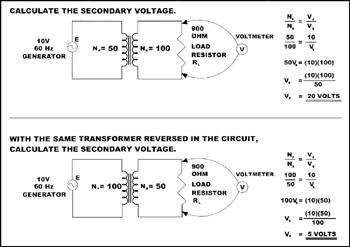
In its simplest form, a transformer consists of two coils that are so near to one another that the magnetic flux caused by exciting current in the first, or primary, coil cuts the three-dimensional space occupied by the second coil, thereby inducing a voltage in the second coil. With this action, it is essentially acting just like a generator's rotating magnetic field. The voltage imparted to the second coil can be calculated simply by the ratio
where N P = the number of turns in the primary coil
N S = number of turns in the secondary coil
V P = voltage measured across the primary coil terminals
V S = voltage generated in the secondary coil
Figure 9-1 is a sample calculation showing how to determine what the voltage will be out of the secondary terminals of a transformer with a given input voltage connected to the primary coil terminals.