Handbook of Electric Power Calculations, Third Edition
A powerful calculations tool for electric power engineers and technicians, this book offers essential, step-by-step procedures and examples for solving a wide array of electric power problems.
Lawrence J.Hollander, P.E.
Dean of Engineering Emeritus
Union College
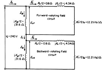
A single-phase induction motor has the following data: 1 hp, two pole, 240 V, 60 Hz, stator-winding resistance R S=1 .6 ?. The no-load test results are V NL=240 V, I NL=3.8 A, P NL=190 W; the locked-rotor test results are V LR=88 V, I LR=9.5 A, P LR=418 W. Establish the equivalent circuit of the motor.
1. Calculate the Magnetizing Reactance, ![]()
The magnetizing reactance essentially is equal to the no-load reactance. From the noload ![]() One-half of this (31.6 ?) is assigned to the equivalent circuit portion representing the forward-rotating mmf waves and the other half to the portion representing the backward-rotating mmf waves. See Fig. 6.1. The no load power, 190 W, represents the rotational losses.
One-half of this (31.6 ?) is assigned to the equivalent circuit portion representing the forward-rotating mmf waves and the other half to the portion representing the backward-rotating mmf waves. See Fig. 6.1. The no load power, 190 W, represents the rotational losses.
2. Calculate the Impedance Values from Locked-Rotor Test
For the locked-rotor test in induction machines, the magnetizing branch of the equivalent circuit is considered to be an open circuit, because the ratio of impedances ![]() is very small. Considering V LR as reference (phase angle=0), use the equation P LR= V LR I LR cos ? LR. Thus, ? LR=cos ?1( P LR/ V LR I LR)=cos ?1[418 W/(88 V)(9.5 A)]=cos ?1 0.5=60 . The effective stator current
is very small. Considering V LR as reference (phase angle=0), use the equation P LR= V LR I LR cos ? LR. Thus, ? LR=cos ?1( P LR/ V LR I LR)=cos ?1[418 W/(88 V)(9.5 A)]=cos ?1 0.5=60 . The effective stator current