Handbook of Electric Power Calculations, Third Edition
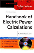
A powerful calculations tool for electric power engineers and technicians, this book offers essential, step-by-step procedures and examples for solving a wide array of electric power problems.
 TABLE OF CONTENTS
 Determine the inductance per phase for a three-phase transmission line consisting of single conductors arranged unsymmetrically (Fig. 9.3).

1. Use Flux-Linkage Method
The principle of obtaining inductance per phase by using the flux linkages of one conductor is utilized once again. If the line is unsymmetrical and it remains untransposed, the inductance for each phase will not be equal (transposition of a line occurs when phases a, b, and c swap positions periodically). Transposing a transmission line will equalize the inductance per phase. Inductance, however, varies only slightly when untransposed, and it is common practice, in hand calculations, to assume transposition as is done in what follows.
Assume phase a shifts from position 1 to 2, and then to 3; phases b and c also move in the rotation cycle. The average flux linkages for phase a are then given by: ? a=(2 10 7)/(3)[(1/4 I a+ I a ln D 12 /a+ I a ln D 13 /a+ I b ln D 2l /a+ I c ln D 31 /a)+(1\4 Ia+ Ia ln D 21 /a+ I a ln D 23 /a+ I b ln D 32 /a+ I c ln D 12/ a)+(1/4+ I a ln D 32/ a+ I