Handbook of Electric Power Calculations, Third Edition
A powerful calculations tool for electric power engineers and technicians, this book offers essential, step-by-step procedures and examples for solving a wide array of electric power problems.
Lawrence J.Hollander, P.E.
Dean of Engineering Emeritus
Union College
The following components comprise a simplified version of a power system, listed in sequential physical order from the generator location to the load: (1) two steam-electric generators, each at 13.2 kV; (2) two step-up transformers, 13.2/66 kV; (3) sending-end, high-voltage bus at 66 kV; (4) one long transmission line at 66 kV; (5) receiving-end bus at 66 kV; (6) a second 66-kV transmission line with a center-tap bus; (7) step-down transformer at receiving-end bus, 66/12 kV, supplying four 12-kV motors in parallel; and (8) a step-down transformer, 66/7.2 kV, off the center-tap bus, supplying a 7.2-kV motor. Draw a one-line diagram for the three-phase, 60-Hz system, including appropriate oil circuit breakers (OCBs).
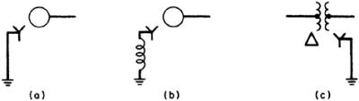
1. Identify the Appropriate Symbols
For electric-power networks an appropriate selection of graphic symbols is shown in Fig. 10.1.

2. Draw the Required System
The system described in the problem is shown in Fig. 10.2. The oil circuit breakers are added at the appropriate points for proper isolation of equipment. diagrams may be drawn that will represent the electric circuitry for positive, negative, and zero-sequence components. Additionally, it is often necessary to identify the grounding connection, or whether the device is wye- or delta-connected. This type of notation is shown in Fig. 10.3.