Varactor Diodes Information
Last revised: October 22, 2024
Reviewed by: Scott Orlosky, consulting engineer
 Varactor diodes are two-terminal electronic components that are designed to provide voltage-controlled capacitance when operated under reverse bias. These simple semiconductors are PN junctions with a positive or P-region with positive ions and a negative or N-region with negative electrons.
Applying voltage to the PN junction causes current to flow in only one direction as electrons from the N-region fill “holes” in the P-region. When the junction is reverse-biased, increasing the applied voltage causes the depletion region to widen, increasing the effective distance between the capacitor plates and decreasing the effective capacitance.
By adjusting the doping gradient and junction width, the capacitance range can be controlled and changes applied using reverse voltage. A four-to-one capacitance range is not unusual. In fact, a typical varactor diode can vary from 60 pf at zero bias to 15 pf at 20 V. With careful manufacturing, however, the capacitance range can be increased to ten-to-one.
Varactor diodes, which are sometimes referred to as varicap diodes, are used in electronic tuning systems to eliminate the need for moving parts.
Specifications
Reverse current or leakage current (IR), the current at which the specified reverse voltage is applied, measures the current that flows when reverse bias is applied to a semiconductor junction.
 Capacitance ratio (CDmin/CDmax) is the ratio of the minimum capacitance and the maximum capacitance. Smaller ratios indicate larger ranges of capacitance.
Terminal capacitance or diode capacitance (CD) is the minimum capacitance when the specified reverse voltage and frequency are applied.
Junction operating temperature (Tj) is the range of temperatures at which diode are designed to operate.
Measured in watts (W), power dissipation (PD) is the maximum power dissipated by the diode while in its “on” state at a specified ambient temperature.
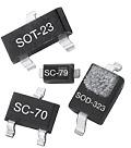
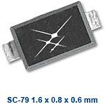
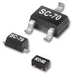
IC Package Types
IC package types for varactor diodes include:
Other varactor diodes are available in a discrete package (DPAK) or in D2PAK, a large surface-mounted package that includes a heat sink.
SC-59, SC-74, and SC-76 are plastic, surface-mounted IC packages with three leads.
Metal electrode leadless face (MELF) diodes have metallized terminals at each end of a cylindrical body and are designed to fit the same footprints as flat components.
QuadroMELF diodes have a square cross section to provide better on board stability and greater "pick and place" accuracy.
MiniMELF is a miniature version of MELF and MicroMELF has the same footprint as the SOD110 and SOD323 packages.
Product Life Stages
 Varactor diodes follow product life style stages that are defined by the Electronic Industries Alliance (EIA) in EIA-724.
Numbered stages range from zero to eight and cover product introduction, growth, maturity, market saturation, phase out, last shipment, and removal.
The first stage, Life Cycle Stage Code 0, describes varactor diodes that are in the planning or early design stages. The last stage, Life Cycle Stage Code 8, describes varactor diodes that are no longer stocked in inventory or available for sale.
Standards
MIL-S-19500/333 — Semiconductor Diode Silicon Varactor Type/1N4386
Varactor Diodes FAQs
How do varactor diodes differ from regular diodes in terms of functionality?
Varactor diodes differ from regular diodes in terms of functionality primarily in their ability to act as voltage-controlled capacitors. Here are the key differences:
Functionality
Regular Diodes: These are primarily used for rectification, allowing current to flow in one direction while blocking it in the opposite direction.
Varactor Diodes: These are designed to act as voltage-controlled capacitors when operated under reverse bias. The capacitance of a varactor diode changes with the applied reverse voltage, which is a unique feature not present in regular diodes.
Capacitance Control
Regular Diodes: Do not have a significant capacitance variation with voltage.
Varactor Diodes: The capacitance decreases as the reverse voltage increases. This property is utilized in applications like electronic tuning systems, where the capacitance needs to be adjusted without mechanical movement.
Applications
Regular Diodes: Commonly used in power conversion, signal demodulation, and protection circuits.
Varactor Diodes: Used in frequency modulation, voltage-controlled oscillators, and RF design due to their variable capacitance properties.
How is the capacitance of a varactor diode controlled?
The capacitance of a varactor diode is controlled by varying the reverse voltage applied across its P-N junction.
Depletion Region
When a reverse voltage is applied to a varactor diode, it creates a depletion region between the P and N regions. This region acts as the dielectric of a capacitor.
Capacitance Variation
The capacitance of the varactor diode is inversely related to the thickness of the depletion region. As the reverse voltage increases, the depletion region widens, effectively increasing the distance between the "plates" of the capacitor, which decreases the capacitance.
Voltage-Capacitance Relationship
The relationship between the reverse voltage and capacitance is nonlinear. As the reverse voltage is decreased, the capacitance increases, which is depicted in the typical varactor voltage-capacitance curve.
Capacitance Range
By adjusting factors such as the doping gradient and junction width, the capacitance range can be controlled. A typical varactor diode can vary from 60 picofarads (pf) at zero bias to 15 pf at 20 volts, and with precise manufacturing, this range can be extended to ten-to-one.
This ability to control capacitance through reverse voltage makes varactor diodes particularly useful in applications like electronic tuning systems, where mechanical movement is undesirable.
What is the significance of the doping gradient in varactor diodes?
The doping gradient in varactor diodes plays a significant role in determining their capacitance characteristics. Here's how it impacts the functionality of varactor diodes:
The doping gradient, along with the junction width, is crucial in controlling the capacitance range of a varactor diode. By adjusting these parameters, manufacturers can influence how the capacitance changes with the applied reverse voltage.
A well-designed doping gradient allows for a wide capacitance range. For instance, a typical varactor diode can vary from 60 picofarads (pf) at zero bias to 15 pf at 20 volts. With precise manufacturing, this range can be extended to a ten-to-one ratio.
The doping gradient affects the non-linear relationship between the reverse voltage and the capacitance. This non-linearity is essential for applications like electronic tuning systems, where precise control over capacitance is required without mechanical adjustments.
In summary, the doping gradient is a critical factor in the design of varactor diodes, influencing their capacitance range and the way capacitance changes with voltage, which is vital for their application in electronic tuning systems and other RF applications.
What are the challenges in manufacturing varactor diodes?
Manufacturing challenges include precise control over the doping gradient and junction width, achieving a high-quality factor (Q), and managing material challenges in compound semiconductor manufacturing. These factors are critical for ensuring the performance and reliability of varactor diodes.
What is the importance of the quality factor (Q) in varactor diodes?
The quality factor (Q) is an important parameter in varactor diodes, particularly in their application within resonant circuits such as LC oscillators. Here's why the quality factor is significant:
The quality factor (Q) of a varactor diode is a measure of its efficiency in storing and releasing energy. It is defined as the ratio of the energy stored to the energy dissipated per cycle. A higher Q indicates lower energy losses and better performance in resonant circuits.
In LC oscillators, the overall quality factor is typically dominated by the inductor's Q. However, the varactor's Q can become significant if it is low, potentially degrading the overall Q of the circuit. This degradation can affect the oscillator's phase noise and power consumption, which are critical parameters in high-frequency applications.
When designing varactor diodes, achieving a high Q is essential to minimize resistive losses and ensure optimal performance. This involves careful material selection and process control during manufacturing to enhance the Q factor.
Varactor diodes with a high Q are particularly valuable in applications like voltage-controlled oscillators (VCOs) and frequency modulation systems, where maintaining low phase noise and efficient energy transfer is crucial.
What are the challenges in achieving a high-quality factor in varactor diodes?
Achieving a high-quality factor (Q) in varactor diodes is challenging due to several factors that need to be carefully managed during design and manufacturing.
The quality factor is influenced by the materials used and the precision of the manufacturing process. Ensuring low resistive losses requires careful selection of materials and stringent control over the manufacturing process to enhance the Q factor.
Designing varactors with a high Q involves balancing the tuning ratio and the quality factor. The tuning ratio, defined as the ratio between the maximum and minimum capacitance values, must be optimized alongside the Q factor to ensure efficient performance in applications like LC oscillators.
A low Q factor in varactor diodes can degrade the overall quality factor of resonant circuits, affecting parameters such as phase noise and power consumption. This is particularly critical in high-frequency applications where maintaining a high Q is essential for optimal performance.
For varactor diodes made from compound semiconductors, unique material challenges such as etch selectivity, feature size control, and wafer handling must be addressed. These challenges can impact the device's performance and reliability, making it difficult to achieve a high Q factor.
These challenges highlight the complexity involved in designing and manufacturing varactor diodes with a high-quality factor, requiring precise control over various parameters to meet the specific needs of their applications.
Varactor Diodes Media Gallery
References
GlobalSpec—High Voltage Diodes
GlobalSpec—Types of Diodes, Their Characteristics and Applications
GlobalSpec—Brewer Science presents innovative material solutions for compound semiconductor manufacturing at CS Mantech
GlobalSpec—Low-Voltage CMOS RF Frequency Synthesizers
Image Credit: