 The industry's most authoritative handbook on flow measurement provides a road map to the field of flow measurement. This best-seller discusses strategies for problem solving and puts the whole array of types of flowmeters at the reader's disposal. The text includes laminar flow elements, critical flowmeters, statistics for measurement, laboratory primary standards, and uncertainty in flow measurement. Emphasis is placed on the importance of accuracy in measurements and ways of ensuring accuracy and avoiding equipment damage through correct forecast of operating conditions, flowmeter selection, installation, calibration, and maintenance. Fundamental considerations such as mixed-phase flow, piping effects, and flow conditioning are examined at length. The problem of attaining a meaningful flow signal through linearization, compensation, and totalization is discussed. Join the thousands of engineers, technicians, managers, and salespeople that have found this reference text an invaluable resource.
Chapter 19 - Turbine Flowmeters
Turbine flowmeters are designed to accurately measure the flow of liquids and gases in pipes. They are volumetric flow measuring devices and have been commercially available since the late 1940s. Sizes exist from a variety of manufacturers to cover the flow range from 0.001 gpm to over 25,000 gpm for liquid service and 0.001 acfm to over 25,000 acfm for gas service. End connections are available to meet the various piping systems. The flowmeters are typically manufactured from austenitic stainless steel but are also available in a variety of materials, including plastic. Turbine meters are applicable to all clean fluids over a pressure range from subatmospheric to over sixty thousand psi and temperature ranges from cryogenic to about 800°C (1500°F). The turbine flowmeter is perhaps the most accurate type of meter available. It is capable of repeating to 0.025% of reading with accuracy and traceability to 0.05% of reading for liquid service; it is also capable of repeating to 0.1% of reading with accuracy and traceability to 0.3% of reading for gas service. A turbine meter has only one moving part - the rotor. Components can be selected for compatibility with most fluids, such as corrosive chemicals, dairy products, cryogenic liquids, steam, fuels, and water (including de-ionized water). The output signal from the flowmeter and sensor is an electronic pulse, but other output signals such as analog, visual, or digital are available. | Advantages:
|
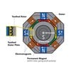
Principles of Operation
A turbine flowmeter consists of a rotor mounted on a bearing and shaft in a
housing. The fluid to be measured in passed through the housing, causing the rotor
to spin with a rotational speed proportional to the velocity of the flowing fluid
within the meter. A device to measure the speed of the rotor is employed to make
the actual flow measurement. The sensor can be a mechanically gear-driven shaft
to a meter or an electronic sensor that detects the passage of each rotor blade generating
a pulse. The rotational speed of the sensor shaft and the frequency of the
pulses is proportional to the volumetric flow rate through the meter.
Figure 19-1 shows a vector diagram of the forces involved. Vector V has an
axial velocity v and no velocity component in the radial or tangential direction.
The lack of a velocity component in the tangential direction is an important element
in the system and will be discussed in more detail. The rotor blade is oriented
at an incidence angle a to the flow stream. The momentum of the flowing
fluid imparts a rotational velocity on the rotor, causing the flow to change direction
and depart from the rotor in a swirling direction. The rotational velocity is
nearly directly proportional to the velocity or flow rate through the flowmeter.