Small Antenna Design

Keeping mathematics to the absolute minimum, this guide describes the theory behind effective small antenna design while providing design techniques and examples for small antennas for different operating frequencies.
 TABLE OF CONTENTS
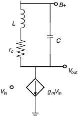
 In the early days of electronic radio, the ability of a receiver to select just one station out of the many with sufficient strength to be detected was determined by the quality of a coil. Figure 3.1 shows a simplified schematic of an RF amplifier. To begin, we assume that the following stage has a very high input impedance so that the load on the active device (a vacuum tube in those days) is just the elements shown. Here r c is the resistance inherent in the coil wire. An ideal (perfect) coil would have no loss resistance. The voltage out of the stage is:

We may further assume that the power into a load further into the receiver is proportional to the square of the output voltage of our stage. This output power is:

where G is a constant representing the power gain of the following stages. Let P m be the maximum power as a function of frequency, and Z m be the maximum magnitude of Z( j ?). Then the normalized power is:
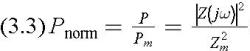
This normalized power is similar in concept to a gain known as transducer power gain (TPG).

When we talk about antenna bandwidth and bandwidth of an antenna-matching network combination, it is with respect to this gain.
Ordinarily we think that the maximum impedance of a parallel-resonant circuit is at the frequency...