Small Antenna Design

Keeping mathematics to the absolute minimum, this guide describes the theory behind effective small antenna design while providing design techniques and examples for small antennas for different operating frequencies.
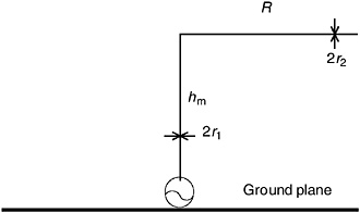
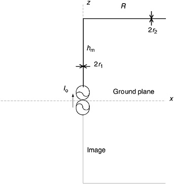
The inverted-L is the simplest case of top loading and it is used occasionally for this reason. It is illustrated in Figure 6.4, with labels to facilitate the discussion. By using the theory of images and some generally-available results for parts of the image-theory structure, we can get analytical approximations for the input impedance. Figure 6.5 shows the image-theory version of the antenna and Figure 6.6 shows an illustration of its current distribution. I assume that the total wire length is short enough to allow me to approximate the current as a triangle function. Since the current doesn t go to zero until the end of the wire, the average value on the vertical section is raised from the minimum of half of the input value. The second benefit of this arrangement is that the radial wire increases the capacitance, which decreases the reactance compared to the simple monopole.
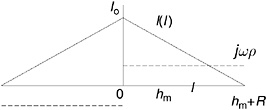
The resistance part of the input impedance is easy; we just need to calculate the average current on the vertical section and use equation (2.39). Figure 6.6 shows the current as a function of length l along the wire. On the vertical section, l = z, and on the upper radial, l = h m+ x. The slope on the right-hand side of Figure 6.6...