Small Antenna Design

Keeping mathematics to the absolute minimum, this guide describes the theory behind effective small antenna design while providing design techniques and examples for small antennas for different operating frequencies.
The meaning of this question is that, very often, people trying to measure some aspect of an antenna s performance are not seeing what they imagine they are measuring. Figure 9.1 illustrates a common problem with impedance and other measurements. The instrument making the measurement is necessarily at some distance from the antenna and is connected through a transmission line, usually a coaxial cable. Whether the load end is grounded or not, the mismatch causes a reflected wave, some of which leaves the feed region and causes a current wave on the outside of the coax. The fact that the reflection is not all in the cable causes a different impedance from that of the antenna itself, and the current on the outside of the cable radiates, making it appear that the antenna is sending out more power than it is by itself.
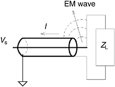
Figure 9.2 shows a generic test range. For pattern and gain measurements, the antenna being tested (device under test, DUT) is in receive mode and a source antenna illuminates the DUT with a nominally plane wave. The DUT is mounted on a rotator capable of 3-D positioning and the transmitted field is stationary. Sounds simple and direct, right? But, as you see, there are possibilities for getting more waves than you want. Indeed, I was looking at a 20-year-old book I ve had since it...