Small Antenna Design

Keeping mathematics to the absolute minimum, this guide describes the theory behind effective small antenna design while providing design techniques and examples for small antennas for different operating frequencies.
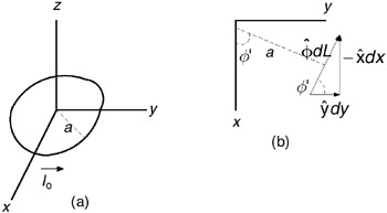
Loop antennas come in a variety of shapes but the most common single-turn shapes are the circle and the rectangle. In this appendix I use results from Appendices A and B to find the radiated field for a small circular loop carrying a uniform (independent of position) current. Figure C.1(a) shows the setup for a loop in the x- y plane, and Figure C.1(b) shows the decomposition of a current-length element. As pointed out in Chapter 2, the vector orientation of the radiated fields depends on the direction of the current source. In electromagnetic theory, the current density is given a vector character, and when current density times volume, ![]() dV, is converted into total current times length, it is the length element that is assigned the vector property to show the direction of current flow as Id
dV, is converted into total current times length, it is the length element that is assigned the vector property to show the direction of current flow as Id ![]() . In the present case, the current flows around the loop in the
. In the present case, the current flows around the loop in the ![]() direction. At each point on the loop, the element of length is ad
direction. At each point on the loop, the element of length is ad ![]() . From Figure C.1(b), we see that this corresponds to a y-directed component of length dy ? = a cos(
. From Figure C.1(b), we see that this corresponds to a y-directed component of length dy ? = a cos( ![]() ) d
) d ![]() and a x-directed component dx ? = a sin(
and a x-directed component dx ? = a sin( ![]() ) d
) d ![]() . From equation (2.3) and Appendix A, if these current length elements were at the origin, their radiated fields would be:
. From equation (2.3) and Appendix A, if these current length elements were at the origin, their radiated fields would be: