Small Antenna Design

Keeping mathematics to the absolute minimum, this guide describes the theory behind effective small antenna design while providing design techniques and examples for small antennas for different operating frequencies.
I only know of two experimental studies of the monopole that cover a wide range of radius and height values. The first was published in 1945 by Brown and Woodward [1, pp. 4 6:4 9] and in the 1960s by students of R. W. P. King [2]. Figure 6.1 illustrates two different ways to drive a thick monopole. Figure 6.1(a) is a coaxial cable below the ground plane with the center conductor extended to make the antenna. This method was used in both sets of measurements. Figure 6.1(b) shows a relatively narrow coax with its center conductor passing through to the base of a thick cylindrical antenna. This method was also used by Brown and Woodward, although the details of the feed geometry are not given.
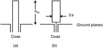
The data in [1] is given as curves in two different formats. The resolution for h m < 0.1 ? for the resistance curves is not very good, but one can draw some general conclusions. For the straight-through coax feed system of Figure 6.1(a), the tighter the coax is, the smaller the reactance magnitude is. The feed system of Figure 6.1(b) has a much lower reactance magnitude than the straight-through cases, and also appears to have lower resistance. The data in [2] is given both in curves and tables, and I use it to verify the modeling results of the next section.
NEC is based on thin-wire theory, so a...