B.1 Minimum Casing Pressure
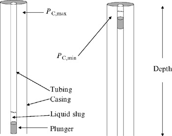
The minimum casing pressure at the moment that the plunger and liquid slug arrive at the surface is given by:
where P P = pressure required to lift the plunger, psi
P C = pressure required to lift one barrel of liquid and overcome friction, psi
S V = liquid slug volume above plunger, bbl
K = factor to account for gas friction below the plunger
D = plunger depth, ft
Approximate values for K and P C are given in Table B-1. In Equation B-1, K is calculated from:
Table B-1: Approximate Values for K and P C from Reference 1 | Tubing Size (inch) | K | P c |
| 2.375 | 33,500 | 165 |
| 2.875 | 45,000 | 102 |
| 3.000 | 57,600 | 67 |
where T avg = the average temperature, F
Z = the average gas deviation factor
? G = the produced gas gravity
f gas = friction factor for gas flow in tubing
V = average gas velocity, ft/sec
OD TBG = tubing OD, inches
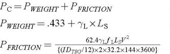
The factor P Cis calculated from:
where ? L = produced liquid gravity
f L = friction factor for liquid flow in tubing
L S =...

 TABLE OF CONTENTS