4.3.1 Constant Strain Triangle
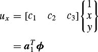
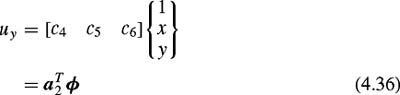
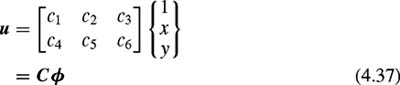
A triangular plane element [3] , [4] with three nodes is shown in Fig. 4.2. The two displacement functions ( u x, u y) at any point within the triangle, expressed in its local coordinate system, have linear variations:
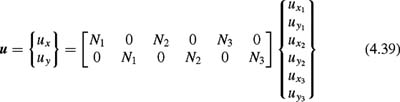
or
 Figure 4.2: Triangular plane element.
 The unknown coefficients c i are evaluated in terms of nodal values of the unknown displacements by applying appropriate boundary conditions at the nodes, i.e., at
Further,
or
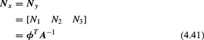
where the interpolation functions N 1, N 2, N 3 in Eq. (4.39) are obtained from the expressions
and
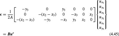
where A is the area of the triangle. To obtain the strain-displacement matrix, the planar strain vector is expressed as
in which
and the required matrix is obtained from Eqs. (4.39), (4.42), and (4.44) as
For the plane stress problem the stress-strain relationship for a general material can be written as
in which
and where ? I is the initial strain vector. For homogeneous, isotropic material, ? x = ? y = ?, so that
Then the stiffness and inertia matrices and thermal and initial load vectors are derived from standard relationships such as
and also
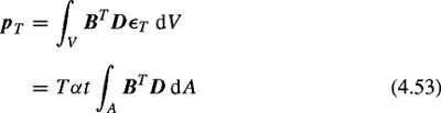
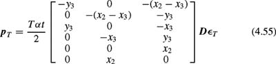
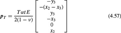
For the constant strain triangle (CST), the thermal nodal forces are calculated to be
In the local coordinate system,
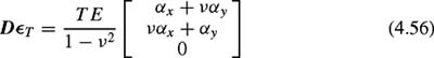
in which
and for homogeneous, isotropic material ? x = ? y = ?,
For initial strains ? I