Electrical Properties Of Materials, Seventh Edition

9.3: Rectification

9.3 Rectification

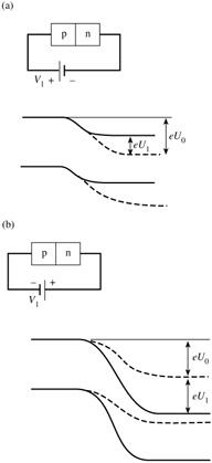
Let us now apply a voltage as shown in Fig. 9.4. Since there are much fewer carriers in the transition region, we may assume that all the applied voltage will drop across the transition region. Then, depending only on the polarity, the potential barrier between the p and n regions will decrease or increase. If the p-side is made positive the potential barrier is reduced, and we talk of forward bias. The opposite case is known as reverse bias; the p-side is then negative, and the potential barrier is increased.


Figure 9.4: The energy diagram of a p-n junction for (a) forward bias and (b) reverse bias.

It is fairly obvious qualitatively that the number of electrons flowing from left to right is not affected in either case. The same number of electrons will still roll down the hill as in equilibrium. But the flow of electrons from right to left is seriously affected. For reverse bias it will be reduced and for forward bias it will significantly increase. So we can see qualitatively that the total current flowing for a voltage U 1 will differ from the current flowing at a voltage - U 1. This is what is meant by rectification.

It is not difficult to derive the mathematical relationships; we have practically everything ready. The current from left to right is the same; let us denote it by I 0. The current from right to left may be obtained...

UNLIMITED FREE
ACCESS
TO THE WORLD'S BEST IDEAS

SUBMIT
Already a GlobalSpec user? Log in.

This is embarrasing...

An error occurred while processing the form. Please try again in a few minutes.

Customize Your GlobalSpec Experience

Category: Diodes
Finish!
Privacy Policy

This is embarrasing...

An error occurred while processing the form. Please try again in a few minutes.