Electronic Warfare Target Location Methods

The analysis of interferometric LOB algorithms using a maximum likelihood approach is presented in this section. The development follows that in [19] closely.
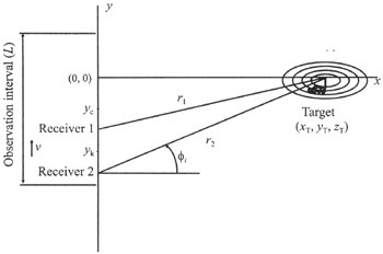
Consider the geometry shown in Figure 2.32, which contains an airborne sensor flying in the +y direction with velocity v. It contains two receivers as noted. Distance y k is at the center of the two receivers at instant k. Measurements are taken over the observation interval, which has a center located at y c. The target is located at coordinates ( x T, y T) (the z-dimension is ignored for now). Initially it is assumed that y T = 0. M = 2 P + 1 measurements are collected over interval L.
The sensor measures the phase difference of the signals received by the two receivers. This difference is related to the ranges r 1 and r 2 by
| (2.240) | |
When the baseline between the two receivers is small compared with the range to the target and the bearing angle is small, the two rays that delineate r 1 and r 2 in Figure 2.32 are approximately parallel, as shown in Figure 2.33. Then
but for small ?,
so
so the error in the range difference, as indicated by the standard deviation ? ? r, is...