Introduction to Communication Systems Simulation

Chapter 6: Modulation

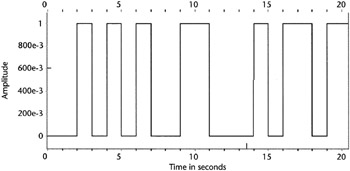
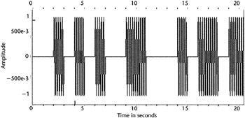
Once the transmitter has produced the final bit stream, the last step is to modulate it onto a suitable carrier. This chapter describes the most commonly used modulations. It is possible to vary only the amplitude, phase, or frequency of a sine wave. So all modulation formats are some theme and variation of using these three possibilities. In general, simulating a modulator is a relatively easy task, much easier than that of the receiver.

Our emphasis in this chapter will be on digital modulation as opposed to standard AM and FM modulation.

6.1 Amplitude Modulation (MASK)

One of the simplest forms of digital modulation is multiple amplitude shift keying (MASK). In its simplest form, a logical [1] is transmitted with some amplitude A, and a logical [0] is not transmitted at all. This format is commonly called on-off keying (OOK). Figure 6.1 shows an input NRZ data, and Figure 6.2 shows the resulting transmitted signal on a carrier. Figure 6.3 shows the same idea with four levels of amplitude, 4ASK, Figure 6.4 shows the corresponding modulated signal.


Figure 6.1: The input NRZ data to be binary ASK modulated.

Figure 6.2: Modulated ASK signal corresponding to the data of Figure 6.1.

Figure 6.3: The amplitude data for 4ASK. The symbol rate is half the bit rate.

Figure 6.4: MASK modulated signal from the data of Figure 6.3.

We can continue this process indefinitely. Take k bits in a group to make one of 2 k amplitudes to be modulated.

UNLIMITED FREE
ACCESS
TO THE WORLD'S BEST IDEAS

SUBMIT
Already a GlobalSpec user? Log in.

This is embarrasing...

An error occurred while processing the form. Please try again in a few minutes.

Customize Your GlobalSpec Experience

Category: RF Receivers
Finish!
Privacy Policy

This is embarrasing...

An error occurred while processing the form. Please try again in a few minutes.