Radar Cross Section Measurements
Presenting and explaining the rules of good measurement practice, this valuable reference explains how RCS is typically measured on test ranges, and how testing may be tailored to meet specific requirements.
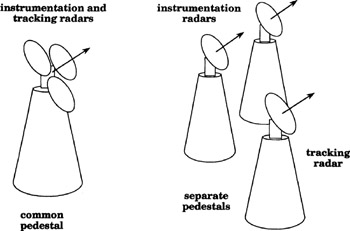
Although it is possible to design and build a radar capable of tracking the target as well as measuring the target echo, it is simpler to assign the tracking and measurement functions to separate radars, and sometimes optical trackers are used. While it is possible to install the antennas for both the instrumentation radar and the tracking system on a common pedestal, as suggested at the left of fig. 11.1, this drives up the cost of the pedestal, especially if the antennas are large. The design issue is largely an electromechanical one of providing enough power to slew the antennas in both azimuth and elevation, and this is governed largely by the required tracking rate and the inertia of the antennas. In some cases it is less costly to acquire a collection of smaller pedestals than one very large one, as shown at the right of fig. 11.1, and to slave them together electrically. The dynamic test system being planned by the U.S. Air Force for installation on the White Sands Missile Range is an example of the latter; see Section 11.5.
That solution to the antenna-slewing problem invites other problems, however. If the tracker antenna is installed on one pedestal, and the instrumentation antennas are installed on one or more other pedestals, tracking algorithms must be developed that account for the difference in the pointing directions...