 | This up-to-date text/reference is designed to present the fundamental principles of robotics with a strong emphasis on engineering applications and industrial solutions based on robotic technology. It can be used by practicing engineers and scientists - or as a text in standard university courses in robotics. The book has extensive coverage of the major robotic classifications, including Wheeled Mobile Robots, Legged Robots, and the Robotic Manipulator. A central theme is the importance of kinematics to robotic principles. The book is accompanied by a CD-ROM with MATLAB simulations, photographs, tutorials, and third-party software (see About the CD-ROM section). |
Robotics
3.5 Using the Parallel Port of the Computer
A port contains a set of signal lines that the CPU uses to send or receive data with other components. Ports are usually used to communicate via modem, printer, keyboard, mouse, etc. In signaling, open signals are 1 and closed signals are 0. A parallel port sends 8 bits and receives 5 bits at a time. The serial port RS-232 sends only 1 bit at a time. However, it is multidirectional. So it can send 1 bit and receive 1 bit at a time. Parallel ports are mainly meant for connecting the printer to the PC. But this port can be programmed for many more applications beyond that.
Parallel ports are easy to program and faster compared to the serial ports. But the main disadvantage is that it needs more number of transmission lines. Because of this reason parallel ports are not used in long-distance communications. You should know the basic difference between working off a parallel port and serial port. In serial ports, there will be two data lines: one transmission and one receiving line. To send data in a serial port, it has to be sent one bit after another with some extra bits like start bit, stop bit, and parity bit to detect errors. But in a parallel port, all the 8 bits of a byte will be sent to the port at a time and an indication will be sent in another line. There will be some data lines, some control, and some handshaking lines in a parallel port.
The D-25 type of female connector is located at the backside of the CPU cabinet and has 25 pins. The pin structure of D-25 is explained in Table 3.5.
TABLE 3.5 Pin Directions and Associated Registers | |||
|---|---|---|---|
| Pin No (D-Type 25) | SPP Signal | Direction In/out | Register.bit |
| 1* 2 3 4 5 6 7 8 9 10 11* 12 13 14* 15 16 17* 18 25 | nStrobe Data 0 Data 1 Data 2 Data 3 Data 4 Data 5 Data 6 Data 7 nAck Busy Paper-Out / Paper-End Select nAuto-Linefeed nError / nFault nInitialize nSelect-Printer/ nSelect-In Ground | In/Out In/Out In/Out In/Out In/Out In/Out In/Out In/Out In/Out In In In In In/Out In In/Out In/Out Gnd | Control.0 Data.0 Data.1 Data.2 Data.3 Data.4 Data.5 Data.6 Data.7 Status.7 Status.6 Status.5 Status.4 Control.1 Status.3 Control.2 Control.3 |
- 8 output pins [D0 to D7]
- 5 status pins [S4 to S7 and S3]
- 4 control pins [C0 to C3]
- 8 ground pins [18 to 25]
In Figure 3.40, let us see how communication between a PC and printer takes place. The computer places the data in the data pins, and then it makes the strobe
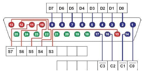
FIGURE 3.40 Pin configuration of D-25.
low. When the strobe goes low, the printer understands that there is valid data in the data pins. Other pins are used to send controls to the printer and get the status of the printer; you can understand them by the names assigned to the pins.
To use the printer port for applications other than printing, we need to know how ports are organized. There are three registers associated with an LPT port: data register, control register, and status register. Data register will hold the data of the data pins of the port. That means, if we store a byte of data to the data register, that data will be sent to the data pins of the port. Similarly with control and status registers. Table 3.6 explains how these registers are associated with ports.
TABLE 3.6 Addresses of Data, Control, and Status Registers | ||
|---|---|---|
| Register | LPT1 | LPT2 |
| Data register (Base Address + 0) | 0x378 | 0x278 |
| Status register (Base Address + 1) | 0x379 | 0x279 |
| Control register (Base Address + 2) | 0x37a | 0x27a |
Pins with an * symbol in this table are hardware inverted. That means, if a pin has a low i.e., 0 V, the corresponding bit in the register will have value 1.
Signals with the prefix n are active low. That means that normally these pins will have low value. When it needs to send some indication, it will become high. For example, normally nStrobe will be high, when the data is placed in the port, the computer makes that pin low.
Normally, data, control, and status registers will have the following addresses. We need these addresses in programming later.
![]() All the parallel ports do not have bidirectional capability. Earlier parallel
ports had only output enabled in data pins since printers only input data. But
later, to make the parallel port capable of communicating with other devices,
bidirectional ports were introduced.
All the parallel ports do not have bidirectional capability. Earlier parallel
ports had only output enabled in data pins since printers only input data. But
later, to make the parallel port capable of communicating with other devices,
bidirectional ports were introduced.
By default, a data port is an output port. To enable the bidirectional property of the port, we need to set the bit 5 of the control register.
To know the details of parallel ports available in your computer, follow this procedure:
- Right click on My Computer, go to Properties.
- Select the tab Hardware, click Device Manager.
- You will get a tree structure of devices; in that expand Ports (Com1 & LPT).
- Double-click on the ECP Printer Port (LPT1) or any other LPT port if available.
- You will get details of the LPT port. Make sure that Use this Port (enable) is selected.
- Select tab resourses. In that you will get the address range of the port.
To start programming, you will need a D-25-type male connector.
Programming the Printer Port in DOS
To start programming the port, we will use DOS. In DOS we have commands to access the port directly. But, these programs will not work on the systems based on Windows XP, Windows NT, or higher versions. For security reasons, higher versions of Windows do not allow accessing the port directly. To program the parallel port in these systems, we need to write to the kernel mode driver. In Section 3.5.2, we will discuss programming the parallel port in Windows XP.
When we want to find out whether a particular pin of the port is high or low, we need to input the value of the corresponding register as a byte. In that, we have to find out whether the corresponding bit is high or low using bitwise operators. We can t access the pins individually. So, you need to know basic bitwise operations.
The main bitwise operators that we need are bitwise AND & and bitwise OR . To make a particular bit in a byte high without affecting other bits, write a byte with corresponding bit 1 and all other bits 0; OR it with the original byte. Similarly, to make a particular bit low, write a byte with corresponding bit 0 and all other bits 1; AND it with the original byte.
In Turbo C, there are the following functions used for accessing the port:
- outportb( PORTID, data);
- data = inportb( PORTID);
- outport( PORTID, data);
- data = inport( PORTID).
The outport() function sends a word to the port, inport() reads a word from the port. outportb() sends a byte to the port and inportb() reads a byte from the port. If you include the DOS.H header, these functions will be considered as macro, otherwise as functions. Function inport() will return a word having lower byte as the data at PORTID and higher byte as the data at PORTID+2. So, we can use this function to read status and control registers together. inportb() function returns byte at PORTID. outport() writes the lower byte to PORTID and higher byte to PORTID+1. So this can be used to write data and
LISTING 3.1 |
|---|
| /* file: ex1.c Displays contents of status register of parallel port. Tested with TurboC 3.0 and Borland C 3.1 for DOS. */ #include stdio.h #include conio.h #include dos.h #define PORT 0x378 void main( ) { int data; clrscr(); while(!kbhit( )) { data=inportb(PORT+1); gotoxy(3,10); printf( Data available in status register: %3d (decimal), %3X (hex)\n , data, data); printf( \n Pin 15: %d ,(data & 0x08)/0x08); printf( \n Pin 13: %d ,(data & 0x10)/0x10); printf( \n Pin 12: %d ,(data & 0x20)/0x20); printf( \n Pin 11: %d ,(data & 0x80)/0x80); printf( \n Pin 10: %d ,(data & 0x40)/0x40); delay(10); } } |
control together. outportb() function writes the data to PORTID. outport() and outportb() return nothing.
Let us start with inputting first. Here is an example program, copy it and run it in Turbo C or Borland C without anything connected to the parallel port. Then you should see data available in the status register and pin numbers 10, 11, 12, 13, and 15 of the parallel port. Pin 11 (active low) is 0 and all other pins are 1 means it is OK.
To understand bitwise operations: you can find data in pin 15, the value of (data & 0x08) will be 0x08 if bit 3 of the register is high, otherwise:
LISTING 3.2 | |
|---|---|
| bit no. 7654 3210 data : XXXX 1XXX & with : 0000 1000 (0x08 ) -> 0000 1000 (0x08 -> bit 3 is high ) | bit no. 7654 3210 data : XXXX 0XXX & with : 0000 1000 (0x08 ) -> 0000 0000 (0x00 -> bit 3 is low) |
We will use the same logic throughout this section.
Now, take a D-25 male with cables connected to each pin. Short all the pins from 18 to 25, call it as ground. Now you can run the above program and see the change by shorting pins 10, 11, 12, 13, and 15 to ground. We prefer using switches between each input pin and ground. Be careful, do not try to ground the output pins.
To find out the availability of ports in a computer programmatically, we will use the memory location where the address of the port is stored.
TABLE 3.7 | |||||
|---|---|---|---|---|---|
| 0x408 | 0x409 | 0x40a | 0x40b | 0x40c | 0x40d |
| LPT1 lowbyte | LPT1 highbyte | LPT2 lowbyte | LPT2 highbyte | LPT3 lowbyte | LPT3highbyte |
If the following code is run in Turbo C or Borland C, the addresses of available ports can be seen. See Listing 3.3.
Next we will check output pins. To check the output, we will use LEDs. We have driven LEDs directly from the port. But it is preferred to connect a buffer to prevent excessive draw of current from the port. Connect an LED in series with a resister of 1KW or 2.2KW between any of the data pins (2 to 9) and ground. With that, if you run the program in Listing 3.4, you should see the LED blinking with app. 1 sec frequency.
LISTING 3.3 |
|---|
| /*PortAdd.c To find availability and addresses of the lpt ports in the computer. */ #include #include void main( ) { unsigned int far *ptraddr; /* Pointer to location of Port Addresses */ unsigned int address; /* Address of Port */ int a; ptraddr=(unsigned int far *)0x00000408; clrscr( ); for (a = 0; a < 3; a++) { address = *ptraddr; if (address == 0) printf( No port found for LPT%d \n ,a+1); else printf( Address assigned to LPT%d is 0x%X \n ,a+1,address); ptraddr++; } getch( ); } |
LISTING 3.4 |
|---|
| #include conio.h #include dos.h #define PORT 0x378 void main( ) { while(!kbhit( )) { outportb(PORT, ~inportb(PORT) ); delay(1000); } } |

FIGURE 3.41 The circuit diagram.
We have made an electrical circuit to show you how our circuit works. It is shown in Figure 3.41. And also we have different angled pictures of the complete circuit in Figure 3.42.
Ok then, let s find out what we have to supply:
- 1 or 2 meter parallel port cable (3 meter is acceptable but the voltage drops from 5 V to 4.7 V).

FIGURE 3.42 Pictures of the complete circuit.
- 9 assembling cables (8 go to resistance and 1 go to ground).
- A breadboard (white one in the picture) or you can solder the cables but with a breadboard you don t have to solder the cables.
- 8 LEDs (2.5 V).
- 8 resistances (470 ohm) (for not to make the LEDs garbage because of +5 V).
- A multimeter (not needed but if something wrong happens you can check the wiring with this).
- Program to make your circuit live.
Interfacing the LCD Module to a Parallel Port
You have seen LCD modules used in many electronic devices like coin phones, billing machines, and weighing machines. It is a powerful display option for stand-alone systems. Because of low power dissipation, high readability, and flexibility for programmers; LCD modules are becoming popular. In this part, we will learn how to connect an LCD module to a PC parallel port and we will prepare some library routines for LCD interfacing.
Before starting our study, let us see why you need to interface an LCD, or Liquid Crystal Display, module to the parallel port.
- If you need to modify the code, you need not have to disconnect the circuit or reprogram the chip as you do in the case of a microcontroller.
- You need to spend less: one LCD module, D-25 female connector, one potentiometer (optional), and some wires this is what you need along with a computer.
- When you are using a computer in full-screen mode like games, movies or TV; you need to exit the application to get small updating information from the computer, i.e., if you need to watch time in that time, you have to close the games. But instead of that you can use an LCD module to display real time from the PC and you can use it along with your application. Real-time implementation from the system clock example is explained in this article. If you are good at programming, you can even connect to the Internet to get news, stock exchange updates, and make them fl ash in the LCD module, only if you found it important, or you can go through it by exiting your application.
LCD modules are available in a wide range like 8x1, 8x2, 16x1, 16x2, 20x2, 20x4, and 40x4. Here we have used 16x2 that means 2 rows of 16 characters. It is a Hitachi HD44780 compatible module, having 16 pins including 2 pins for backlight.
Table 3.8 gives the pin structure of an LCD module. LCD modules without backlight will have only 14 pins. If you are using such LCDs, simply ignore the 15th and 16th pins.
TABLE 3.8 Pin Description of a HitachiHD44780 LCD | ||
|---|---|---|
| Pin No | Symbol | Details |
| 1 2 3 4 5 6 7 to 14 15 16 | GND Vcc Vo RS R/W E D0 to D7 VB1 VB0 | Ground Supply Voltage +5V Contrast adjustment 0-> Control input, 1-> Data input Read/Write Enable Data Backlight +5V Backlight ground |
To program the LCD module, first we have to initialize the LCD by sending some control words. RS should be low and E should be high when we send control. R/W pin 0 means write data or control to LCD and R/W pin 1 means read data from the LCD. To send data to an LCD, make RS high, R/W low, place the data in pins 7 to 14, and make pin E high and low once. You can understand the exact method after seeing the code, later in this Chapter. To make this let us first build a circuit.
Here, we are going to write on the LCD module and not read back. So, R/W is connected to the ground directly. We need not have to input any data through, so all output pins are used in our application. Data pins of the LCD are connected to data pins of the port. Strobe signal (pin 1 of D-25 connector) is given to E (pin 6 of the LCD). Select printer (pin 17 of D-25) is connected to RS (pin 4 of the LCD).
In Figure 3.43, the LCD module is connected to the lpt port using a D-25 male connector. Pin number 3 of the LCD is for adjusting the contrast, con-

FIGURE 3.43 Connection diagram.

FIGURE 3.44 An LCD in the on position.
nected in such a way that it can be varied from 0 V to 5 V. Keep it to 0 initially.
If everything is OK, you should get the LCD module as in Figure 3.44 when the power is switched on.
If you get this screen, then we can start programming (See Fig. 3.44). Otherwise check your connections, try by varying the 10K potentiometer. If you get this display also, you can get maximum clearness by varying the pot. Here, pot was needed to be nearly 0 V. So, it is OK if you don t use pot, just connect pin 3 to the ground.
Table 3.9 explains how to write control words. When RS=0 and R/W=0, data in the pins D0 to D7 will have the following meaning.
We have left other instructions related to the read and write LCD RAM area; we will see them later. Using this information, we will write some routines for basic functions of LCDs. Now look at our first program below. Here we have written functions for all our needs in LCD interfacing. So, in our next program, we are going to change our main function only. You can save these functions as a library and include them in your next programs if you want.
#include <dos.h>
#include <string.h>
#include <conio.h>
#include <time.h>
#define PORTADDRESS 0x378 /* Enter Your Port Address Here */
#define DATA PORTADDRESS+0
#define STATUS PORTADDRESS+1
#define CONTROL PORTADDRESS+2
TABLE 3.9 | |||||||||
|---|---|---|---|---|---|---|---|---|---|
| Instruction | D7 | D6 | D5 | D4 | D3 | D2 | D1 | D0 | Description |
| Clear display | 0 | 0 | 0 | 0 | 0 | 0 | 0 | 1 | Clears display and returns cursor to home position. |
| Cursor home | 0 | 0 | 0 | 0 | 0 | 0 | 1 | X | Returns cursor to home position. Also returns display being shifted to the original position. |
| Entry mode set | 0 | 0 | 0 | 0 | 0 | 1 | I/D | S | I/D = 0 > cursor is in decrement position. I/D = 1 > cursor is in increment position. S = 0 > Shift is invisible. S = 1 > Shift is visible. |
| Display ON-OFF control | 0 | 0 | 0 | 0 | 1 | D | C | B | D- Display, C- cursor, B- Blinking cursor = 0 —> OFF =1 —> ON |
| Cursor/Display shift | 0 | 0 | 0 | 1 | S/C | R/L | X | X | S/C = 0 —> Move cursor. S/C = 1 —> Shift display. R/L = 0 —> Shift left. R/L = 1 —> Shift right |
| Function set | 0 | 0 | 1 | DL | N | F | X | X | DL = 0 —> 4-bit interface. DL = 1 —> 8-bit interface. N = 0 —> 1/8 or 1/11 Duty (1 line). N = 1 —> 1/16 Duty (2 lines). F = 0 —> 5x7 dots. F = 1 —> 5x10 dots. |
void lcd_init(void);
void lcd_write(char char2write);
void lcd_putch(char char2write);
void lcd_puts(char * str2write);
void lcd_goto(int row, int column);
void lcd_clear(void);
void lcd_home(void);
void lcd_cursor(int cursor);
void lcd_entry_mode(int mode);
void main(void)
{
lcd_init();
lcd_goto(1,1);
lcd_puts(“Welcome To”);
lcd_goto(1,0);
lcd_puts(“Appin Knowledge Solutions”);
while(!kbhit() ) //wait until a key is pressed...
{}
}
void lcd_init()
{
outportb( CONTROL, inportb(CONTROL) & 0xDF); //config data pins as
output
outportb(CONTROL, inportb(CONTROL) 0x08);
//RS is made high: control (register select)
lcd_write(0x0f);
delay(20);
lcd_write( 0x01);
delay(20);
lcd_write( 0x38);
delay(20);
}
void lcd_write(char char2write)
{
outportb( DATA, char2write);
outportb(CONTROL,inportb(CONTROL) 0x01); /* Set Strobe */
delay(2);
outportb(CONTROL,inportb(CONTROL) & 0xFE);/* Reset Strobe */
delay(2);
}
void lcd_putch(char char2write)
{
outportb(CONTROL, inportb(CONTROL) & 0xF7);
//RS=low: data
lcd_write(char2write);
}
void lcd_puts(char *str2write)
{
outportb(CONTROL, inportb(CONTROL) & 0xF7);
//RS=low: datawhile(*str2write)
lcd_write(*(str2write++));
}
void lcd_goto(int row, int column)
{
outportb(CONTROL, inportb(CONTROL) 0x08);
if(row==2) column+=0x40;/*
Add these if you are using LCD module with 4 columnsif(row==2)
column+=0x14;
if(row==3) column+=0x54;
*/lcd_write(0x80 column);
}
void lcd_clear()
{
outportb(CONTROL, inportb(CONTROL) 0x08);
lcd_write(0x01);
}
void lcd_home()
{
outportb(CONTROL, inportb(CONTROL) 0x08);
lcd_write(0x02);
}
void lcd_entry_mode(int mode)
{
/*
if you dont call this function, entry mode sets to 2 by
default.mode: 0 - cursor left shift, no text shift
1 - no cursor shift, text right shift
2 - cursor right shift, no text shift
3 - no cursor shift, text left shift
*/
outportb(CONTROL, inportb(CONTROL) 0x08);
lcd_write(0x04 + (mode%4));
}
void lcd_cursor(int cursor)
{
/*
set cursor: 0 - no cursor, no blink
1 - only blink, no cursor
2 - only cursor, no blink
3 - both cursor and blink
*/
outportb( CONTROL, inportb(CONTROL) 0x08 );
lcd_write( 0x0c + (cursor%4));
}
We need not give details to all the functions above. You can understand them yourself. So, try using all the functions. In the next examples, we will generate a program that displays the system time in the LCD module. It may not have much use in DOS, but if you transfer the same to Windows, you will gain many benefits. Also, if your computer will be working in DOS most of the time, you can think of writing a TSR for the same.
In order to program to display date and time in an LCD module just replace the main of the previous program with the following and run.
void main(void)
{
struct time t;
struct date d;
char strtime[17];
textbackground(0);
clrscr();
textcolor(0);
textbackground(10);
gotoxy(8,5);
cputs(“ “);
gotoxy(8,4);
cputs(“ “);
lcd_init();
lcd_cursor(0);
while(!kbhit())
{
gettime(&t);
getdate(&d);
lcd_goto(0,4);
sprintf(strtime,”%02d:%02d:%02d”, t.ti_hour%12, t.ti_min,
t.ti_sec);
lcd_puts(strtime);
gotoxy(12,4);
cputs(strtime);
lcd_goto(1,3);
sprintf(strtime,”%02d:%02d:%4d”, d.da_day, d.da_mon,
d.da_year);
lcd_puts(strtime);
gotoxy(11,5);
cputs(strtime);
delay(200);
}
textbackground(0);
textcolor(7);
}
© 2006-2026 Infinity Science Press. All rights reserved.