 | This up-to-date text/reference is designed to present the fundamental principles of robotics with a strong emphasis on engineering applications and industrial solutions based on robotic technology. It can be used by practicing engineers and scientists - or as a text in standard university courses in robotics. The book has extensive coverage of the major robotic classifications, including Wheeled Mobile Robots, Legged Robots, and the Robotic Manipulator. A central theme is the importance of kinematics to robotic principles. The book is accompanied by a CD-ROM with MATLAB simulations, photographs, tutorials, and third-party software (see About the CD-ROM section). |
Robotics
3.2.3 Breadboard
Circuits can be modeled to make sure they work the way you want them to. Circuit modeling can be done either using a computer modeling application, or on a prototype board also called a breadboard or Vero board which is a board covered with small sockets into which components can be plugged and connected up.
Figure 3.9 shows a breadboard with holes connected in two long rows at the top and bottom, and columns of five linked holes elsewhere. Electronic components and wires can be simply plugged into the board in order to make any required circuit connections. The top and bottom rows act as power supply channels for the circuit.

FIGURE 3.8 (a) An electrolytic capacitor and (b) its schematic symbol and name.
A breadboard prototype for a 555 mono stable timer circuit might look like this:
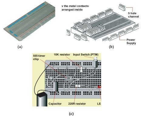
FIGURE 3.9 (a) A breadboard, (b) internal connection of a breadboard,
and (c) a symbolic representation of a 555 mono stable timer circuit on a
breadboard.
Evaluation and Testing
Evaluation and testing is about making sure that the product stays on track with the design specification. You should plan to evaluate and test your project at a number of key stages of design and manufacture. These stages are referred to as critical control points.
The critical control points for evaluation and testing an electronic product are:
- Initial Design Phase: Check that you have used the correct value components, and that the various systems work together. These checks can be done using a computer-simulation package.
- Breadboard Phase: Use the breadboard to check whether the circuit works properly. Test each part of the circuit using a millimeter or logic probe.
- PCB Layout: Check that the components are in the correct positions and that you have used the optimum track layout. Make sure that the components are located neatly and that joints are well soldered.
- Manufacturing and Packaging Phase: After manufacture, check that the product conforms to its specification. During packaging, check that the product fits securely in the package, and that any conducting parts are insulated.
- Finally, the Analysis Phase: Look back over the design and making process. Analyze how well it went, noting any modifications and improvements you would make if you were to do it again. These notes are an important part of your design portfolio.
© 2006-2026 Infinity Science Press. All rights reserved.