 | This up-to-date text/reference is designed to present the fundamental principles of robotics with a strong emphasis on engineering applications and industrial solutions based on robotic technology. It can be used by practicing engineers and scientists - or as a text in standard university courses in robotics. The book has extensive coverage of the major robotic classifications, including Wheeled Mobile Robots, Legged Robots, and the Robotic Manipulator. A central theme is the importance of kinematics to robotic principles. The book is accompanied by a CD-ROM with MATLAB simulations, photographs, tutorials, and third-party software (see About the CD-ROM section). |
Robotics
3.2.4 Potentiometer
A potentiometer (or pot, for short) is a manually adjustable, variable resistor. It is commonly used for volume and tone controls in stereo equipment. On the RoboBoard a 10k pot is used as a contrast dial for the LCD screen, and the RoboKnob of the board is also a potentiometer.
In robotics, a potentiometer can be used as a position sensor. A rotary potentiometer (the most common type) can be used to measure the rotation of a shaft. Gears can be used to connect the rotation of the shaft being measured to the potentiometer shaft. It is easiest to use if the shaft being measured does not need to rotate continuously (like the second hand on a clock), but rather rotates back and forth (like the pendulum on a grandfather clock). Most potentiometers rotate only about 270 degrees; some can be rotated continuously, but the values are the same on each rotation. By using a gear ratio other than 1:1, the position of a shaft that rotates more than 270 degrees can be measured.
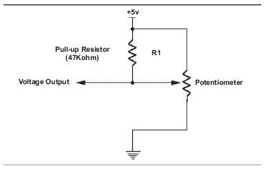
FIGURE 3.10 Potentiometer circuit.
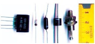
FIGURE 3.11 Diodes.
A potentiometer connected to a shaft and a lever can also be used to determine the distance to a wall and to make the robot follow a path parallel to the wall. The lever, perhaps with a small wheel on the end, would extend from the side of the robot and contact the wall; a rubber band would provide a restoring force. If the robot moved closer to the wall, the lever would pivot, turning the shaft and the potentiometer. The control program would read the resulting voltage and adjust the robot steering to keep the voltage constant.
Electrical Data
Potentiometers have three terminals. The outer two terminals are connected to a resistor and the resistance between them is constant (the value of the potentiometer). The center terminal is connected to a contact that slides along the resistance element as the shaft is turned, so the resistance between it and either of the other terminals varies (one increases while the other decreases). The assembly instructions suggest wiring the potentiometer in the voltage divider configuration, with the on-board pull-up resistor in parallel with one of the potentiometer s two effective resistances. This will yield readings of greater precision (although they will not be linear) than if the pot were used as a two-terminal variable resistor. You may want to try different circuits to determine which works best for your application.
© 2006-2026 Infinity Science Press. All rights reserved.