 | This up-to-date text/reference is designed to present the fundamental principles of robotics with a strong emphasis on engineering applications and industrial solutions based on robotic technology. It can be used by practicing engineers and scientists - or as a text in standard university courses in robotics. The book has extensive coverage of the major robotic classifications, including Wheeled Mobile Robots, Legged Robots, and the Robotic Manipulator. A central theme is the importance of kinematics to robotic principles. The book is accompanied by a CD-ROM with MATLAB simulations, photographs, tutorials, and third-party software (see About the CD-ROM section). |
Robotics
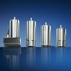
3.8.4 Stepper Motors
The shaft of a stepper motor moves between discrete rotary positions typically separated by a few degrees. Because of this precise position controllability, stepper motors are excellent for applications that require high positioning accuracy. Stepper motors are used in X-Y scanners, plotters, and machine tools, floppy and hard disk drive head positioning, computer printer head positioning, and numerous other applications.
Stepper motors have several electromagnetic coils that must be powered sequentially to make the motor turn, or step, from one position, to the next. By
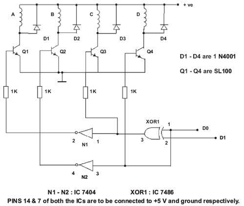
FIGURE 3.63
reversing the order that the coils are powered, a stepper motor can be made to reverse direction. The rate at which the coils are respectively energized determines the velocity of the motor up to a physical limit. Typical stepper motors have two or four coils. Anyway, here is a very simple stepper controller shown in Figure 3.63.
How Stepper Motors Work
We ve all experimented with small hobby motors, or free-spinning DC motors. Have you ever tried to position something accurately with one? It can be pretty difficult. Even if you get the timing just right for starting and stopping the motor, the armature does not stop immediately. DC motors have very gradual acceleration and declaration curves; stabilization is slow. Adding gears to the motor will help to reduce this problem, but overshoot is still present and will throw off the anticipated stop position. The only way to effectively use a DC motor for precise positioning is to use a servo. Servos usually implement a small DC motor, a feedback mechanism (usually a potentiometer attached to the shaft by gearing or other means), and a control circuit which compares the position of the motor with the desired position, and moves the motor accordingly. This can get fairly complex and expensive for most hobby applications.
Stepper motors, however, behave differently than standard DC motors. First of all, they cannot run freely by themselves. Stepper motors do as their name suggests they step a little bit at a time. Stepper motors also differ from DC motors in their torque-speed relationship. DC motors generally are not very good at producing high torque at low speeds, without the aid of a gearing mechanism. Stepper motors, on the other hand, work in the opposite manner. They produce the highest torque at low speeds. Stepper motors also have another characteristic, holding torque, which is not present in DC motors. Holding torque allows a stepper motor to hold its position firmly when not turning. This can be useful for applications where the motor may be starting and stopping, while the force acting against the motor remains present. This eliminates the need for a mechanical brake mechanism. Steppers don t simply respond to a clock signal, they have several windings which need to be energized in the correct sequence before the motor s shaft will rotate. Reversing the order of the sequence will cause the motor to rotate the other way. If the control signals are not sent in the correct order, the motor will not turn properly. It may simply buzz and not move, or it may actually turn, but in a rough or jerky manner. A circuit which is responsible for converting step and direction signals into winding energization patterns is called a translator. Most stepper motor control systems include a driver in addition to the translator, to handle the current drawn by the motor s windings.
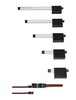
Figure 3.64 shows a basic example of the translator + driver type of configuration. Notice the separate voltages for logic and for the stepper motor. Usually the motor will require a different voltage than the logic portion of the system. Typically, logic voltage is +5 Vdc and the stepper motor voltage can range

FIGURE 3.64 A typical translator/driver connection.
from +5 Vdc up to about +48 Vdc. The driver is also an open collector driver, wherein it takes its outputs to GND to activate the motor s windings. Most semiconductor circuits are more capable of sinking (providing a GND or negative voltage) than sourcing (outputting a positive voltage).
Common Characteristics of Stepper Motors
Stepper motors are not just rated by voltage. The following elements characterize a given stepper motor:
Voltage
Stepper motors usually have a voltage rating. This is either printed directly on the unit, or is specified in the motor s datasheet. Exceeding the rated voltage is sometimes necessary to obtain the desired torque from a given motor, but doing so may produce excessive heat and/or shorten the life of the motor.
Resistance
Resistance-per-winding is another characteristic of a stepper motor. This resistance will determine current draw of the motor, as well as affect the motor s torque curve and maximum operating speed.
Degrees per Step
This is often the most important factor in choosing a stepper motor for a given application. This factor specifies the number of degrees the shaft will rotate for each full step. Half-step operation of the motor will double the number of steps/ revolutions, and cut the degrees-per-step in half. For unmarked motors, it is often possible to carefully count, by hand, the number of steps per revolution of the motor. The degrees per step can be calculated by dividing 360 by the number of steps in 1 complete revolution. Common degree/step numbers include: 0.72, 1.8, 3.6, 7.5, 15, and even 90. Degrees per step are often referred to as the resolution of the motor. As in the case of an unmarked motor, if a motor has only the number of steps/revolutions printed on it, dividing 360 by this number will yield the degree/step value.
Types of Stepper Motors
Stepper motors fall into two basic categories: permanent magnet and variable reluctance. The type of motor determines the type of drivers, and the type of translator used. Of the permanent magnet stepper motors, there are several subflavors available. These include the unipolar, bipolar, and multiphase varieties.
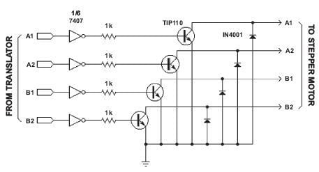
FIGURE 3.65 A typical unipolar stepper motor driver circuit. Note the 4 back EMF protection diodes.
Permanent Magnet Stepper Motors
Unipolar Stepper Motors
Unipolar motors are relatively easy to control. A simple 1-of- n counter circuit
can generate the proper stepping sequence, and drivers as simple as 1
transistor per winding are possible with unipolar motors. Unipolar stepper
motors are characterized by their center-tapped windings. A common wiring
scheme is to take all the taps of the center-tapped windings and feed them
+MV (Motor Voltage). The driver circuit would then ground each winding to
energize it.
Unipolar stepper motors are recognized by their center-tapped windings. The number of phases is twice the number of coils, since each coil is divided in two. So the diagram above (Figure 3.65), which has two center-tapped coils, represents the connection of a 4-phase unipolar stepper motor.
In addition to the standard drive sequence, high-torque and half-step drive sequences are also possible. In the high-torque sequence, two windings are active at a time for each motor step. This two-winding combination yields around 1.5 times more torque than the standard sequence, but it draws twice the current. Half-stepping is achieved by combining the two sequences. First, one of the windings is activated, then two, then one, etc. This effectively doubles the number of steps the motor will advance for each revolution of the shaft, and it cuts the number of degrees per step in half.

FIGURE 3.66 Unipolar stepper motor coil setup (left) and 1-phase drive pattern (right).
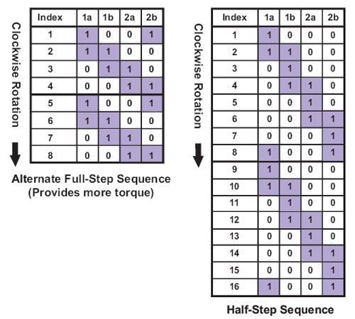
FIGURE 3.67 Two-phase stepping sequence (left) and half-step sequence (right).
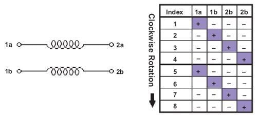
FIGURE 3.68 Bipolar stepper motor coil setup (left) and drive pattern (right).
Bipolar Stepper Motors
Unlike unipolar stepper motors, bipolar units require more complex driver circuitry. Bipolar motors are known for their excellent size/torque ratio, and provide more torque for their size than unipolar motors. Bipolar motors are designed with separate coils that need to be driven in either direction (the polarity needs to be reversed during operation) for proper stepping to occur. This presents a driver challenge. Bipolar stepper motors use the same binary drive pattern as a unipolar motor, only the 0 and 1 signals correspond to the polarity of the voltage applied to the coils, not simply on-off signals. Figure 3.68 shows a basic 4-phase bipolar motor s coil setup and drive sequence.
A circuit known as an H-bridge (Figure 3.69) is used to drive bipolar stepper motors. Each coil of the stepper motor needs its own H-bridge driver circuit. Typical bipolar steppers have 4 leads, connected to two isolated coils in the motor. ICs specifically designed to drive bipolar steppers (or DC motors) are available (popular are the L297/298 series from ST Microelectronics, and the LMD18T245 from National Semiconductor). Usually these IC modules only contain a single H-bridge circuit inside of them, so two of them are required for driving a single bipolar motor. One problem with the basic (transistor) H-bridge circuit is that with a certain combination of input values (both 1 s) the result is that the power supply feeding the motor becomes shorted by the transistors. This could cause a situation where the transistors and/or power supply may be destroyed. A small XOR logic circuit was added in Figure 3.69 to keep both inputs from being seen as 1 s by the transistors.
Another characteristic of H-bridge circuits is that they have electrical brakes that can be applied to slow or even stop the motor from spinning freely when not

FIGURE 3.69 A typical H-bridge circuit. The 4 diodes clamp inductive kickback.
moving under control by the driver circuit. This is accomplished by essentially shorting the coil(s) of the motor together, causing any voltage produced in the coils during rotation to fold back on itself and make the shaft difficult to turn. The faster the shaft is made to turn, the more the electrical brakes tighten.
Variable Reluctance Stepper Motors
Sometimes referred to as hybrid motors, variable reluctance stepper motors are the simplest to control over other types of stepper motors. Their drive sequence

FIGURE 3.70 Variable reluctance stepper motor coil setup (left) and drive pattern (right).
is simply to energize each of the windings in order, one after the other (see drive pattern table below). This type of stepper motor will often have only one lead, which is the common lead for all the other leads. This type of motor feels like a DC motor when the shaft is spun by hand; it turns freely and you cannot feel the steps. This type of stepper motor is not permanently magnetized like its unipolar and bipolar counterparts.
Example Translator Circuits
In this section, examples of basic stepper motor translation circuits are shown. Not all of these examples have been tested, so be sure to prototype the circuit before soldering anything.
Figure 3.71 illustrates the simplest solution to generating a one-phase drive sequence. For unipolar stepper motors, the circuit in Figure 3.71, or for bipolar stepper motors, the circuit in Figure 3.72 can be connected to the 4 outputs of this circuit to provide a complete translator + driver solution. This circuit is limited in that it cannot reverse the direction of the motor. This circuit would be most useful in applications where the motor does not need to change directions.

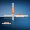
FIGURE 3.71 A simple, single-direction, single-phase drive translator.
Figure 3.72 is a translator for a two-phase operation (believed to have originated from The Robot Builders Bonanza) book, by Gordon McComb. We have used this circuit in the past and seem to recall that it had a problem. This may not

FIGURE 3.72 A simple, bidirectional, two-phase drive stepper motor translator circuit.
be the case when you reverse the direction and continue stepping, the motor will advance one more step in the previous direction it was going before responding. As always, prototype this circuit to be sure it will work for your application before you build anything with it.
There are several standard stepper motor translation circuits that use discrete logic ICs. Below you will find yet another one of these. The circuit in Figure 3.73 has not been tested, but theoretically should work without problems.
Words of Caution
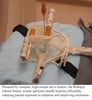
When making connections to either a PC parallel port, or I/O pins of a microcontroller, be sure to isolate the motor well. High-voltage spikes of several hundred volts are possible as back EMF from the stepper motor coils. Always use clamping diodes to short these spikes back to the motor s power bus. The use of optical isolation devices (optoisolators) will add yet another layer or protection between the delicate control logic and the high-voltage potentials which may be present in the power output stage. Whenever possible, use separate power supplies for the motor and the translator/microcontroller. This further reduces the chance of destructive voltages reaching the controller, and reduces or eliminates power supply noise that may be introduced by the motor.

FIGURE 3.73 Another example of a two-phase drive translator circuit, this time using a
multiplexer.
Complete Software Control
Under complete software control, there is no translator circuit external to the parallel port or microcontroller. This scheme reduces parts count, component cost, and makes for simpler board design. On the other hand, it places the responsibility of generating all of the sequencing signals on the software. If the PC or microcontroller is not fast enough (due to code inefficiency or slow processor speed), or too many motors are driven simultaneously, things can begin to slow down. Interrupts and other system events can plague the control software more in this case. Despite the downfalls of addressing a stepper motor directly in this manner, it is definitely the easiest and most straightforward approach to controlling a stepper motor. This method of controlling a motor can also be useful where the hardware is not critical at first and a simple interface is needed to allow more time to be spent on the development of the software before the hardware is refined.
© 2006-2026 Infinity Science Press. All rights reserved.