 | This up-to-date text/reference is designed to present the fundamental principles of robotics with a strong emphasis on engineering applications and industrial solutions based on robotic technology. It can be used by practicing engineers and scientists - or as a text in standard university courses in robotics. The book has extensive coverage of the major robotic classifications, including Wheeled Mobile Robots, Legged Robots, and the Robotic Manipulator. A central theme is the importance of kinematics to robotic principles. The book is accompanied by a CD-ROM with MATLAB simulations, photographs, tutorials, and third-party software (see About the CD-ROM section). |
Robotics
3.8.2 Controlling a DC Motor
Speed, Torque, and Gear Reduction
It was mentioned earlier that the power delivered by a motor is the product of its speed and the torque at which the speed is applied. If one measures this power over the full range of operating speeds from unloaded full speed to stall one gets a bell-shaped curve of motor power output.
When unloaded, the motor is running at full speed, but at zero torque, thus producing zero power. Conversely, when stalled, the motor is producing its maximum torque output, but at zero speed also producing zero power! Hence, the maximum power output must lie somewhere in between, at about one-half of the maximum speed and of the maximum torque.
A typical DC motor operates at speeds that are far too high to be useful, and at torques that are far too low. Gear reduction is the standard method by which a motor is made useful.
The motor shaft is fitted with a gear of small radius that meshes with a gear of large radius. The motor s gear must revolve several times in order to cause the large gear to revolve once (see Figure 3.53). The speed of rotation is thus decreased, but overall power is preserved (except for losses due to friction) and therefore the torque must increase. By ganging together several stages of this gear reduction, a strong torque can be produced at the final stage.
The challenge when designing a high-performance gear reduction for a competitive robot is to determine the amount of reduction that will allow the motor to operate at highest efficiency. If the normal operating speed of a motor/ gear-train assembly is faster than the peak efficiency point, the gear-train will
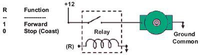
FIGURE 3.53
be able to accelerate quickly, but will not be operating at peak efficiency once it has reached the maximum velocity. Remember that the wheel is part of the drive train and gearing, and its size, the velocity desired, the motor characteristics, and other factors all affect the optimum gear ratio. While calculations can provide a guide, experimentation is necessary to determine the best gear-train.
H-bridge
You take a battery; hook the positive side to one side of your DC motor. Then you connect the negative side of the battery to the other motor lead. The motor spins forward. If you swap the battery leads the motor spins in reverse.
Ok, that s basic. Now lets say you want a Micro Controller Unit (MCU) to control the motor, how would you do it? Well, for starters you get a device that would act like a solid state switch, a transistor, and hook it up to the motor.
![]() If you connect up these relay circuits, remember to put a diode across the
coil of the relay. This will keep the spike voltage (back EMF), coming out of the
coil of the relay, from getting into the MCU and damaging it. The anode, which
is the arrow side of the diode, should connect to ground. The bar, which is the
cathode side of the diode, should connect to the coil where the MCU connects
to the relay.
If you connect up these relay circuits, remember to put a diode across the
coil of the relay. This will keep the spike voltage (back EMF), coming out of the
coil of the relay, from getting into the MCU and damaging it. The anode, which
is the arrow side of the diode, should connect to ground. The bar, which is the
cathode side of the diode, should connect to the coil where the MCU connects
to the relay.
If you connect this circuit to a small hobby motor you can control the motor with a processor (MCU, etc.). Applying a logical one, (+12 volts in our example) to point A causes the motor to turn forward. Applying a logical zero, (ground) causes the motor to stop turning (to coast and stop).
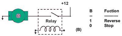
FIGURE 3.54
Hook the motor up in this fashion and the circuit turns the motor in reverse when you apply a logical one (+12 volts) to point B. Apply a logical zero, which is usually a ground, and the motor stops spinning.
If you hook up these circuits you can only get the motor to stop or turn in one direction, forward for the first circuit or reverse for the second circuit.
Motor Speed
You can also pulse the motor control line, (A or B) on and off. This powers the motor in short bursts and gets varying degrees of torque, which usually translates into variable motor speed.
But if you want to be able to control the motor in both forward and reverse with a processor, you will need more circuitry. You will need an H-bridge. Notice the H -looking configuration in Figure 3.55. Relays configured in this fashion make an H-bridge. The high side drivers are the relays that control the positive voltage to the motor. This is called sourcing current.
The low side drivers are the relays that control the negative voltage to sink current to the motor. Sinking current is the term for connecting the circuit to the negative side of the power supply, which is usually ground.
So, you turn on the upper left and lower right circuits, and power flows through the motor forward, i.e., 1 to A, 0 to B, 0 to C, and 1 to D.
Then for reverse you turn on the upper right and lower left circuits and power flows through the motor in reverse, i.e., 0 to A, 1 to B, 1 to C, and 0 to D.
Caution: You should be careful not to turn on both circuits on one side and the other, or you have a direct short which will destroy your circuit; for example: A and C or B and D both high (logical 1).
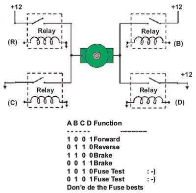
FIGURE 3.55
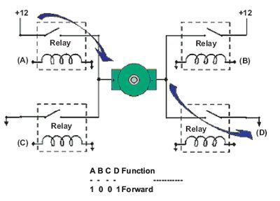
FIGURE 3.56
Semiconductor H-bridges
We can better control our motor by using transistors or Field Effect Transistors (FETs). Most of what we have discussed about the H-bridge relays is true of these circuits. You don t need diodes that were across the relay coils now. You should use diodes across your transistors though. See Figure 3.56 see how they are connected.
These solid state circuits provide power and ground connections to the motor, as did the relay circuits. The high side drivers need to be current sources which is what PNP transistors and P-channel FETs are good at. The low side drivers need to be current sinks which is what NPN transistors and N-channel FETs are good at.
If you turn on the two upper circuits, the motor resists turning, so you effectively have a breaking mechanism. The same is true if you turn on both of the lower circuits. This is because the motor is a generator and when it turns it generates a voltage. If the terminals of the motor are connected (shorted), then the voltage generated counteracts the motors freedom to turn. It is as if you are applying a similar but opposite voltage to the one generated by the motor being turned. Vis- -vis, it acts like a brake.
To be nice to your transistors, you should add diodes to catch the back voltage that is generated by the motor s coil when the power is switched on and off. This flyback voltage can be many times higher than the supply voltage! If you don t use diodes, you could burn out your transistors.
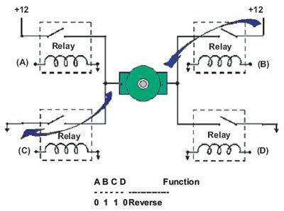
FIGURE 3.57
Transistors, being a semiconductor device, will have some resistance, which causes them to get hot when conducting much current. This is called not being able to sink or source very much power, i.e., not able to provide much current from ground or from plus voltage.
Mosfets are much more efficient, they can provide much more current and not get as hot. They usually have the flyback diodes built in so you don t need the diodes anymore. This helps guard against flyback voltage frying your MCU.
To use mosfets in an H-bridge, you need P-channel mosfets on top because they can source power, and N-channel mosfets on the bottom because then can sink power. N-channel mosfets are much cheaper than P-channel mosfets, but N-channel mosfets used to source power require about 7 volts more than the supply voltage, to turn on. As a result, some people manage to use N-channel mosfets, on top of the H-bridge, by using cleaver circuits to overcome the breakdown voltage.
It is important that the four quadrants of the H-bridge circuits be turned on and off properly. When there is a path between the positive and ground side of the H-bridge, other than through the motor, a condition exists, called shoot through. This is basically a direct short of the power supply and can cause semiconductors to become ballistic in circuits with large currents flowing. There are H-bridge chips available that are much easier, and safer, to use than designing your own H-bridge circuit.
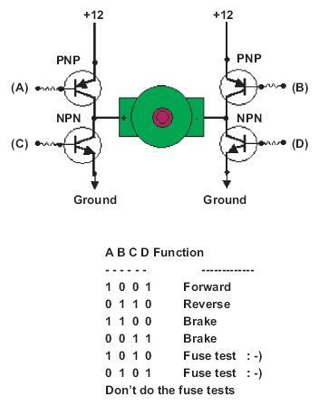
FIGURE 3.58
H-bridge Devices
The L293 has 2 H-bridges, can provide about 1 amp to each and occasional peak loads to 2 amps. Motors typically controlled with this controller are near the size of a 35 mm film plastic canister.
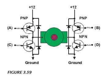
FIGURE 3.59
The L298 has 2 H-bridges on board, can handle 1 amp, and peak current draws to about 3 amps. You often see motors between the size of a 35 mm film plastic canister and a coke can, driven by this type of H-bridge. The LMD18200 has one H-bridge on board, can handle about 2 or 3 amps, and can handle a peak of about 6 amps. This H-bridge chip can usually handle an average motor about the size of a coke. There are several more commercially designed H-bridge chips as well.
There! That s the basics about motors and H-bridges! Hope it helps and be safe!
Darlington Connection
This is two transistors connected together so that the current amplified by the first is amplified further by the second transistor. The overall current gain is equal to the two individual gains multiplied together:
Darlington pair current gain, hFE = hFE1 hFE2
(hFE1 and hFE2 are the gains of the individual transistors).
This gives the Darlington pair a very high current gain, such as 10,000, so that only a tiny base current is required to make the pair switch on.
A Darlington pair behaves like a single transistor with a very high current gain. It has three leads (B, C, and E) which are equivalent to the leads of a standard individual transistor. To turn on there must be 0.7 V across both the base-emitter junctions who are connected in series inside the Darlington pair, therefore it requires 1.4 V to turn on.
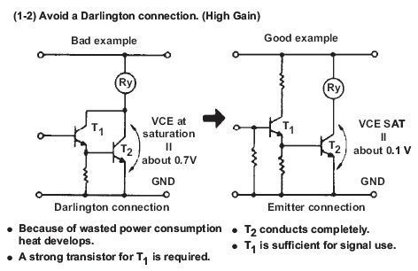
FIGURE 3.60
Darlington pairs are available as complete packages but you can make up your own from two transistors; TR1 can be a low power type, but normally TR2 will need to be high power. The maximum collector current Ic(max) for the pair is the same as Ic(max) for TR2.
A Darlington pair is sufficiently sensitive to respond to the small current passed by your skin and it can be used to make a touch-switch as shown in Figure 3.61. For this circuit, which just lights an LED, the two transistors can be any general-purpose low-power transistors. The 100kΩ resistor protects the transistors if the contacts are linked with a piece of wire.
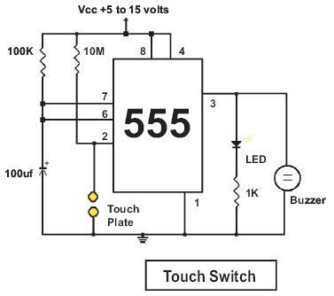
FIGURE 3.61 Touch switch circuit.
© 2006-2026 Infinity Science Press. All rights reserved.