 | This up-to-date text/reference is designed to present the fundamental principles of robotics with a strong emphasis on engineering applications and industrial solutions based on robotic technology. It can be used by practicing engineers and scientists - or as a text in standard university courses in robotics. The book has extensive coverage of the major robotic classifications, including Wheeled Mobile Robots, Legged Robots, and the Robotic Manipulator. A central theme is the importance of kinematics to robotic principles. The book is accompanied by a CD-ROM with MATLAB simulations, photographs, tutorials, and third-party software (see About the CD-ROM section). |
Robotics
3.8 Actuators
An actuator is the mechanism by which an agent acts upon an environment. The agent can be either an artificial intelligent agent or any other autonomous being.
The common forms of actuators are pneumatic, hydraulic, or electric solenoids or motors.
Pneumatic actuators: A simplified diagram of a pneumatic actuator is shown in Figure 3.49 below. It operates by a combination of force created by air and spring force. The actuator positions control the valve by transmitting its motion through the stem.
A rubber diaphragm separates the actuator housing into two air chambers. The upper chamber receives a supply of air through an opening in the top of the housing.
The bottom chamber contains a spring that forces the diaphragm against mechanical stops in the upper chamber. Finally, a local indicator is connected to the stem to indicate the position of the valve.
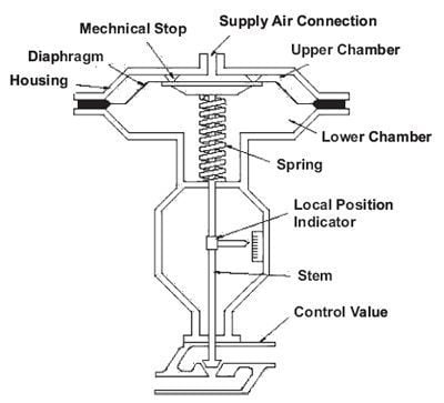
FIGURE 3.49 Pneumatic actuator: air-to-close/spring-to-open.
The position of the valve is controlled by varying the air supply pressure in the upper chamber. This results in a varying force on the top of the diaphragm. Initially, with no air supply, the spring forces the diaphragm upward against the mechanical stops and holds the valve fully open. As air supply pressure is increased from zero, its force on top of the diaphragm begins to overcome the opposing force of the spring. This causes the diaphragm to move downward and the control valve to close.
With increasing air supply pressure, the diaphragm will continue to move downward and compress the spring until the control valve is fully closed. Conversely, if air supply pressure is decreased, the spring will begin to force the diaphragm upward and open the control valve. Additionally, if supply pressure is held constant at some value between zero and maximum, the valve will position at an intermediate position. Therefore, the valve can be positioned anywhere between fully open and fully closed in response to changes in air supply pressure.
A positioner is a device that regulates the air supply pressure to a pneumatic actuator. It does this by comparing the actuator s demanded position with the control valve s actual position. The demanded position is transmitted by a pneumatic or electrical control signal from a controller to the positioner. The pneumatic actuator in Figure 3.49 is shown in Figure 3.50 with a controller and positioner added.
The controller generates an output signal that represents the demanded position. This signal is sent to the positioner. Externally, the positioner consists of an input connection for the control signal, an air supply input connection, an air supply output connection, an air supply vent connection, and a feedback linkage. Internally, it contains an intricate network of electrical transducers, airlines, valves, linkages, and necessary adjustments. Other petitioners may also provide controls for local valve positioning and gauges to indicate air supply pressure and air control pressure (for pneumatic controllers). From an operator s viewpoint, a description of the complex internal workings of a positioner is not needed. Therefore, this discussion will be limited to inputs to and outputs from the positioner.
In Figure 3.50, the controller responds to a deviation of a controlled variable from the setpoint and varies the control output signal accordingly to correct the

FIGURE 3.50 Pneumatic actuator with controller and
positioner.
deviation. The control output signal is sent to the positioner, which responds by increasing or decreasing the air supply to the actuator. Positioning of the actuator and control valve is fed back to the positioner through the feedback linkage. When the valve has reached the position demanded by the controller, the positioner stops the change in air supply pressure and holds the valve at the new position. This, in turn, corrects the controlled variable s deviation from the setpoint.
For example, as the control signal increases, a valve inside the positioner admits more air supply to the actuator. As a result, the control valve moves downward. The linkage transmits the valve position information back to the positioner. This forms a small internal feedback loop for the actuator. When the valve reaches the position that correlates to the control signal, the linkage stops air supply flow to the actuator. This causes the actuator to stop. On the other hand, if the control signal decreases, another valve inside the positioner opens and allows the air supply pressure to decrease by venting the air supply. This causes the valve to move upward and open.
When the valve has opened to the proper position, the positioner stops venting air from the actuator and stops movement of the control valve.
An important safety feature is provided by the spring in an actuator. It can be designed to position a control valve in a safe position if a loss of air supply occurs. On a loss of air supply, the actuator in Figure 3.50 will fail to open. This type of arrangement is referred to as air-to-close, spring-to-open or simply fail-open. Some valves fail in the closed position. This type of actuator is referred to as airto- open, spring-to-close or fail-closed. This fail-safe concept is an important consideration in nuclear facility design.
Hydraulic actuators: Pneumatic actuators are normally used to control processes requiring quick and accurate responses, as they do not require a large amount of motive force. However, when a large amount of force is required to operate a valve (for example, the main steam system valves), hydraulic actuators are normally used. Although hydraulic actuators come in many designs, piston types are the most common.
A typical piston-type hydraulic actuator is shown in Figure 3.51. It consists of a cylinder, piston, spring, hydraulic supply and returns line, and stem. The piston slides vertically inside the cylinder and separates the cylinder into two chambers. The upper chamber contains the spring and the lower chamber contains hydraulic oil.
The hydraulic supply and return line is connected to the lower chamber and allows hydraulic fluid to flow to and from the lower chamber of the actuator. The stem transmits the motion of the piston to a valve.
Initially, with no hydraulic fluid pressure, the spring force holds the valve in the closed position. As fluid enters the lower chamber, pressure in the chamber increases. This pressure results in a force on the bottom of the piston opposite to the force caused by the spring. When the hydraulic force is greater than the

FIGURE 3.51 Hydraulic actuator.
spring force, the piston begins to move upward, the spring compresses, and the valve begins to open. As the hydraulic pressure increases, the valve continues to open. Conversely, as hydraulic oil is drained from the cylinder, the hydraulic force becomes less than the spring force, the piston moves downward, and the valve closes. By regulating the amount of oil supplied or drained from the actuator, the valve can be positioned between fully open and fully closed.
The principles of operation of a hydraulic actuator are like those of the pneumatic actuator. Each uses some motive force to overcome spring force to move the valve. Also, hydraulic actuators can be designed to fail-open or fail-closed to provide a fail-safe feature.
Electric solenoid actuators: A typical electric solenoid actuator is shown in Figure 3.52. It consists of a coil, armature, spring, and stem. The coil is connected to an external current supply. The spring rests on the armature to force it downward. The armature moves vertically inside the coil and transmits its motion through the stem to the valve. When current flows through the coil, a magnetic field forms around the coil. The magnetic field attracts the armature toward the center of the coil. As the armature moves upward, the spring collapses and the valve opens. When the circuit is opened and current stops flowing to the coil, the magnetic field collapses. This allows the spring to expand and shut the valve.

FIGURE 3.52 Electric solenoid actuator.
A major advantage of solenoid actuators is their quick operation. Also, they are much easier to install than pneumatic or hydraulic actuators. However, solenoid actuators have two disadvantages. First, they have only two positions: fully open and fully closed. Second, they don t produce much force, so they usually only operate relatively small valves.
Motors
This chapter introduces several types of motors commonly used in robotic and related applications.
© 2006-2026 Infinity Science Press. All rights reserved.