 | This up-to-date text/reference is designed to present the fundamental principles of robotics with a strong emphasis on engineering applications and industrial solutions based on robotic technology. It can be used by practicing engineers and scientists - or as a text in standard university courses in robotics. The book has extensive coverage of the major robotic classifications, including Wheeled Mobile Robots, Legged Robots, and the Robotic Manipulator. A central theme is the importance of kinematics to robotic principles. The book is accompanied by a CD-ROM with MATLAB simulations, photographs, tutorials, and third-party software (see About the CD-ROM section). |
Robotics
3.8.5 Servo Motor
A servo motor has three wires: power, ground, and control. The power and ground wires are simply connected to a power supply. Most servo motors operate from five volts.
The control signal consists of a series of pulses that indicate the desired position of the shaft. Each pulse represents one position command. The length of a pulse in time corresponds to the angular position. Typical pulse times range from 0.7 to 2.0 milliseconds for the full range of travel of a servo shaft. Most servo shafts have a 180-degree range of rotation. The control pulse must repeat every 20 milliseconds. There are no servo motors in the present ELEC 201 kit.
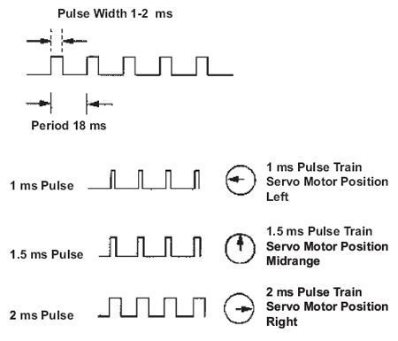
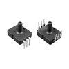
FIGURE 3.74
Servo Motors
Servo motors incorporate several components into one device package:
- a small DC motor;
- a gear reduction drive for torque increase;
- an electronic shaft position sensing and control circuit.
The output shaft of a servo motor does not rotate freely, but rather is commanded to move to a particular angular position. The electronic sensing and control circuitry the servo feedback control loop drives the motor to move the shaft to the commanded position. If the position is outside the range of movement of the shaft, or if the resisting torque on the shaft is too great, the motor will continue trying to attain the commanded position.
Servo motors are used in model radio-controlled airplanes and helicopters to control the position of wing flaps and other flight control mechanisms.
Servo Motor Control
A servo motor has three wires: power, ground, and control. The power and ground wires are simply connected to a power supply. Most servo motors operate from five volts.
The servo controller receives position commands through a serial connection, which can be provided by using one I/O pin of another microcontroller, or a PCs serial port! The communication protocol, that is used for this controller, is the same with the protocol of all the famous servo controllers of Scott Edwards Electronics Inc., this makes this new controller 100% compatible with all the programs that have been written for the SSC controllers! However, if you want to write your own software, it is as easy as sending positioning data to the serial port as follows:
Byte1 = Sync (255)
Byte2 = Servo #(0 15)
Byte3 = Position (0 254)
So sending a 255, 4,150 would move servo 4 to position 150, sending 255,12,35 would move servo 12 to position 35.
The standards of the serial communication should be the following: 9600 baud, 8 data bits, 1 stop bit, and no parity.
The control signal consists of a series of pulses that indicate the desired position of the shaft. Each pulse represents one position command. The length of a pulse in time corresponds to the angular position. Typical pulse times range from 0.7 to 2.0 milliseconds for the full range of travel of a servo shaft. Most servo shafts have a 180-degree range of rotation. The control pulse must repeat every 20 milliseconds. This pulse signal will cause the shaft to locate itself at the midway position +/-90 degrees. The shaft rotation on a servo motor is limited to approximately 180 degrees (+/-90 degrees from center position). A 1 ms pulse will rotate the shaft all the way to the left, while a 2 ms pulse will turn the shaft all the way to the right. By varying the pulse width between 1 and 2 ms, the servo motor shaft can be rotated to any degree position within its range.
© 2006-2026 Infinity Science Press. All rights reserved.