Chip Resistors Information
Last revised: October 16, 2024
Reviewed by: Scott Orlosky, consulting engineer
 Chip resistors are integrated circuit (IC) devices manufactured in square or rectangular chip packages. Resistors are components that oppose the flow of electrical current. They can be used to protect, operate, or control circuits. Resistors can have a fixed value of resistance, or they may be variable or adjustable within a certain range. As passive components, resistors can only reduce voltage or current signals and cannot increase them. Resistors — particularly chip resistors — make up the building blocks of many modern electronic devices.
Resistance
The resistance of an element measures its opposition to electric flow, expressed in ohms (Ω). Every material has a specific resistivity, which measures the strength of this opposition. For an even cross section of an element, the resistance (R) is proportional to the material's resistivity (ρ) and length (L), and inversely proportional to area (A).
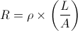
This principle is analogous to a water pipe, where congestion (larger ρ) and longer paths (larger L) make flow more difficult (increasing R), while wider or large diameter sections (larger A) improve flow (decreasing R). Consequently, the construction (size, shape, and material type) of a resistor determines its resistance value, as described in the table below.
Specifications
Packaging
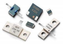
Chip resistors are typically surface mount devices (SMD) in that they do not have leads like through hole technology (THT) devices. Instead, they are mounted directly onto a printed circuit board (PCB). Chip resistors are almost always square or rectangular, with the length and width of the device determining their power ratings. They are constructed in a variety of ways depending on the particular characteristics that are desired.
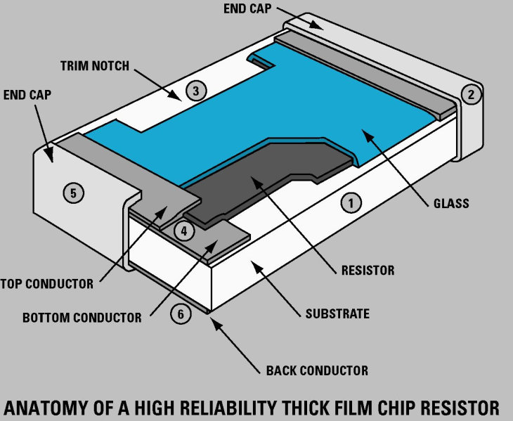
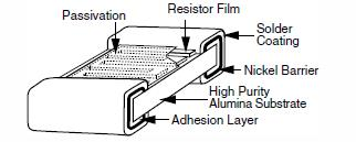
A cross-section of a thick film chip resistor. Image credit: Mini-Systems Inc.
|
Imperial designation |
Metric designation |
Typical power rating (W) |
|
01005 |
0402 |
0.031 |
|
0201 |
0603 |
0.05 |
|
0402 |
1005 |
0.1 or 0.062 |
|
0603 |
1608 |
0.1 |
|
0805 |
2012 |
0.125 |
|
1206 |
3216 |
0.25 |
|
1210 |
3225 |
0.5 |
|
1812 |
4532 |
0.75 |
|
2010 |
5025 |
0.75 |
|
2512 |
6332 |
1 |
The accompanying table illustrates the most common chip resistor sizes and designations. A chip's nominal dimensions can easily be determined by dividing its metric designation in two and placing a decimal point between the numerals of each pair. For example, a 0402 chip measures 0.4 mm x 0.2 mm, while an 1812 package measures 1.8 mm x 1.2 mm; the latter package also features a higher power rating due to its larger size.
Resistor Technology
Chip resistors may use a variety of technology or construction types, each with significant advantages and disadvantages. Some common types are listed below.
Thin film technology relies on the deposition of a thin metallic coating onto a ceramic substrate. Thin film resistors feature very high resistance per given area, making them economical and space-efficient. Disadvantages include the film's susceptibility to failure due to elevated temperatures, water vapor, and chemical contamination.
A thin film resistor. Image credit: EEWeb
Thick film resistors are produced by stenciling a resistive metallic paste onto a base. They provide high resistance per area and cost much less than comparable technologies such as wirewound resistors. While their frequency response is comparable to foil and thin film devices, thick film resistors are much noisier. Despite their drawbacks, they are widely used in circuit sections requiring less precision and durability.
Foil resistors feature a metal foil applied to a ceramic substrate, which has been photo-etched with a resistive pattern. This process creates a resistor with the favorable characteristics of high stability, non-inductance, low capacitance, and low noise without sacrificing accuracy and speed.
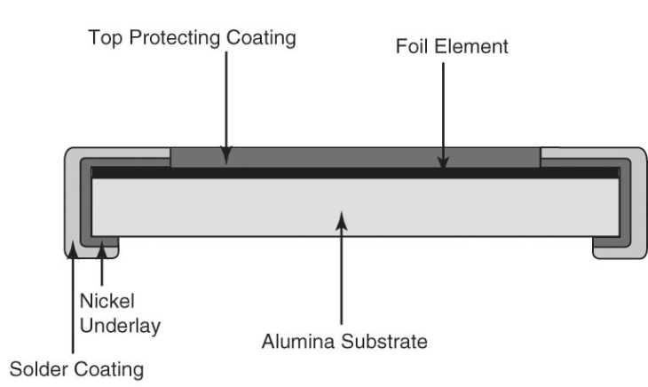
Metal Foil Resistor. Image credit: EETimes
Standards
Chip resistors may be designed, manufactured, and tested according to various standards. Common chip resistor standards include:
- BS EN 140401-801 — Specification for rectangular low power SMD resistors
- Fixed film chip resistors
- Film chip resistors
Chip Resistor FAQs
What is the structure of the chip resistor electrodes and how are they are plated?
The electrodes of chip resistors are typically composed of multiple layers to ensure good electrical conductivity and mechanical stability.
The base layer is usually made of a conductive material such as copper or a copper alloy.
On top of the base layer, there is often a barrier layer made of nickel. This layer serves to prevent the diffusion of the base material into the solder and to enhance the adhesion of the subsequent layers.
The final layer is the plating layer, which is usually made of tin or a tin alloy. This layer provides a good surface for soldering and helps to protect the underlying layers from oxidation and corrosion.
The plating process involves depositing the tin or tin alloy layer onto the nickel barrier layer. This is typically done using an electroplating method, where the chip resistors are submerged in a plating bath containing the plating material. An electric current is then passed through the bath, causing the plating material to be deposited onto the electrodes.
The thickness of the plating layer is carefully controlled to ensure optimal solderability and reliability of the chip resistors. These structural elements and the plating process are crucial for ensuring the performance and longevity of chip resistors in various applications.
How is the failure rate of chip resistors calculated?
The failure rate of chip resistors is calculated using several factors that contribute to the overall reliability of the component. The calculation involves the following parameters:
Basic Failure Rate (λb):
This is the inherent failure rate of the resistor under standard conditions without any additional stress factors.
Temperature Factor (λT):
This factor accounts for the effect of operating temperature on the failure rate. Higher temperatures typically increase the failure rate.
Electric Power Factor (λP):
This factor considers the impact of the electrical power applied to the resistor. Higher power levels can lead to increased failure rates.
Electric Power Stress Factor (λS):
This factor takes into account the stress caused by electrical power, which can vary depending on the application and operating conditions.
Quality Factor (λQ):
This factor reflects the quality of the manufacturing process and materials used in the resistor. Higher quality components generally have lower failure rates.
Environmental Factor (λE):
This factor includes the effects of environmental conditions such as humidity, vibration, and other external influences that can affect the reliability of the resistor.
The overall failure rate (λ) can be expressed as a combination of these factors:
λ=λb⋅λT⋅λP⋅λS⋅λQ⋅λE
This formula provides a comprehensive way to estimate the failure rate of chip resistors by considering various contributing factors.
How do environmental factors affect the performance of chip resistors?
The temperature at the ends of the resistor is lower than in the middle, creating a "Hot Spot" temperature. This hot spot determines both the resistor's stability and lifespan. If the temperature exceeds the specified operating range, the resistance value can change, leading to performance degradation.
TCR (Temperature Coefficient of Resistance) specifications help predict shifts in resistance under different operating temperatures. High operating temperatures can cause resistance drift, impacting the resistor's performance over time
High moisture content in the environment can degrade the performance of resistors. Moisture can lead to corrosion and other forms of degradation that affect the resistor's reliability and longevity.
Mechanical damage can occur during shipping, manufacturing, or service. Improper mounting can also stress the resistor, leading to changes in its electrical parameters and potentially causing failure.
Constant overload conditions generate excessive heat, which can degrade the resistor's performance over time or cause it to fail in extreme cases.
The ambient temperature surrounding the resistor affects its performance. According to MIL standards, the failure rate of chip resistors is influenced by the ambient temperature, among other factors.
Humidity can induce changes in resistance. While high-quality components and proper PCB layout can mitigate some of these effects, humidity remains a factor that can impact resistor performance.
Factors such as the voltage coefficient (change in resistance with voltage) and thermal electromotive force (EMF) due to temperature differences between leads and self-heating can also affect resistor performance. These factors are generally small but can be significant in precision applications.
Over long periods, resistors can exhibit drift in their resistance values due to environmental factors. For example, operating a resistor at high temperatures for extended periods can cause a small drift in resistance, which may stabilize over time.
What is the impact of TCR on chip resistors?
TCR is defined as the relative change in resistance per degree Celsius change in temperature. It is usually expressed in parts per million per degree Celsius (ppm/°C). The formula for TCR is:
TCR=ΔR/R⋅ΔT×10-6
where:
- (ΔR) is the change in resistance,
- (R) is the original resistance,
- (ΔT) is the change in temperature.
The TCR is usually expressed in parts per million per degree Celsius (ppm/°C)
TCR specifications help engineers predict how the resistance of a chip resistor will shift under different operating temperatures. This is crucial for applications where precise resistance values are necessary, such as in voltage divider circuits.
The stability of a resistor is influenced by its TCR. High TCR values can lead to significant resistance changes with temperature fluctuations, affecting the stability and lifespan of the resistor. The "Hot Spot" temperature, which is the maximum temperature in the middle of the resistor body, plays a significant role in determining both stability and lifespan.
Various environmental and electrical factors, such as ambient temperature, humidity, and mechanical stress, can cause the performance of a resistor to degrade over time. TCR helps in understanding how these factors will impact the resistor's performance.
Over long periods, resistors can exhibit drift in their resistance values due to environmental factors such as persistent high temperature.
TCR shows how resistors behave under both cold and high operating temperatures. High operating temperatures can cause resistance drift, impacting the resistor's performance over time. This is particularly important in applications where resistors are exposed to varying temperatures.
According to MIL standards, the failure rate of chip resistors is influenced by several factors, including the temperature factor (λT). This indicates that temperature and, by extension, TCR, play a role in the overall reliability and expected lifespan of chip resistors.
Understanding the TCR of chip resistors is essential for ensuring their reliable performance in various applications. It helps in predicting resistance shifts, maintaining stability, and assessing the long-term reliability of the resistors under different environmental conditions.
Chip Resistor Media Gallery
References
GlobalSpec—Current Sensing Resistors
GlobalSpec—Resistors
- Aerospace
- Automotive
- Bulk Pack
- Carbon Composition
- Carbon Film
- Ceramic Composition
- Current Sensing Resistor
- Fireproof Case
- General Use
- Heat Sink
- High-Current Resistor
- High-Frequency Resistor
- High-Voltage Resistor
- IEC
- Medical
- Metal Alloy
- Metal Film
- Metal Foil
- Metal Oxide
- Military Standards
- Non-Flame Coating
- Non-Inductive
- Power Resistor
- Precision Resistor
- Resistor Chip Array
- RoHS Compliant
- Shipping Tube / Stick Magazine
- Single Resistor
- Surge Resistor
- Tape Reel
- Telecom Resistor
- Thick Film
- Thin Film
- Tray
- UL
- Wirewound Resistor