Intuitive Analog Circuit Design

Chapter 15: Review of Passive Components and a Case Study in PC Board Layout

In This Chapter

Some of the subtleties of passive components including construction techniques of these devices and parasitic effects are considered. We ll cover some details about resistors, capacitors and inductors. Then, we ll use what we ve learned in an illustrative discussion of PC board layout issues.

Resistors

At first blush, a resistor is a resistor is a resistor. However, we ll now delve into some of the subtleties of these devices. The impedance of an ideal resistor is not dependent on operating frequency, [1] and is:


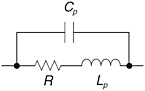
A real-world resistor (Figure 15-1) includes a parasitic inductance due to the geometry of the lead length, and a parasitic capacitance across the resistor. The impedance of the resistor, including these parasitic elements, is: [2]


Figure 15-1: Resistor R showing parasitic elements series inductance L p and parallel capacitance C p.

We can put this in j ? form by making the substitution s = j ? resulting in:


For a large-valued resistor, [3] the RC time constant dominates. This is because a large resistor will swamp out the value of the parasitic inductance. For a low-valued resistor the L/R time constant dominates because the resistor effectively shorts out the parasitic capacitance. The magnitude of the impedance of the real-world resistor is:


In Figure 15-2, we see the impedance of a resistor with R = 1 M ?, C = 0.2 pF and L = 10 nH. Note that for this relatively large resistor...

UNLIMITED FREE
ACCESS
TO THE WORLD'S BEST IDEAS

SUBMIT
Already a GlobalSpec user? Log in.

This is embarrasing...

An error occurred while processing the form. Please try again in a few minutes.

Customize Your GlobalSpec Experience

Category: Chip Resistors
Finish!
Privacy Policy

This is embarrasing...

An error occurred while processing the form. Please try again in a few minutes.