Applied SolidWorks

Providing step-by-step instructions along with numerous illustrations, this book begins at a very basic level and ends at a fairly advanced level so that users can learn Solidworks on their own with little or no outside help.
The Extrude dialog box will appear. SolidWorks also provides a preview of the extrusion. If SolidWorks gave you an error message, there are opens (non-connected lines) somewhere on the sketch. Check each intersection for opens by using the Extend Entities and Trim Entities commands. Your screen should look similar to Figure 77.
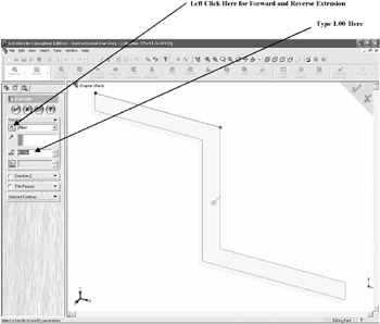
Figure 77
Left click on the icon under Direction, located next to the text Blind . The extrusion will change directions. Ensure that the extrusion is facing forward. While the text located next to D1 is still highlighted, enter 1.000. To preview the extruded part, left click on the Glasses icon located at the top of the Extrude dialog box as shown in Figure 78. The part will become purple.
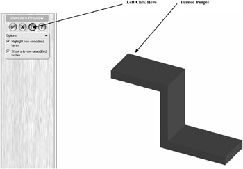
Figure 78
To end preview, left click on the Glasses icon again. This will return the part to the previous view.
Left click on the green checkmark as shown in Figure 79.
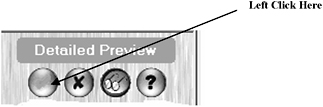
Figure 79