Applied SolidWorks
Providing step-by-step instructions along with numerous illustrations, this book begins at a very basic level and ends at a fairly advanced level so that users can learn Solidworks on their own with little or no outside help.
Create a simple sketch using the Sketch commands
Dimension a sketch using the Smart Dimension command
Revolve a sketch using the Revolve command
Create a hole using the Extrude command
Create a series of holes using the Circular Hole command
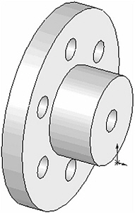
Chapter 2 includes instruction on how to design the part shown below.
Start SolidWorks by referring to Chapter 1 Getting Started .
After SolidWorks is running, begin a new sketch.
Move the cursor to the upper left corner of the screen and left click on Line as shown in Figure 1.

Figure 1
Move the cursor to the lower left portion of the screen and left click once. This will be the beginning end point of a line as shown in Figure 2.
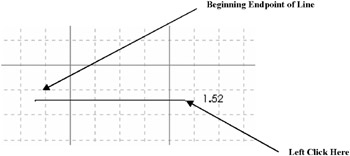
Figure 2
Move the cursor to the right and left click once as shown in Figure 2.
Move the cursor up and left click once as shown in Figure 3.
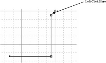
Figure 3
Move the cursor to the right and left click once as shown in Figure 4.
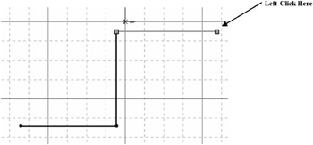
Figure 4
Move the cursor up and left click once as shown in Figure 5.
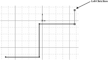
Figure 5
Move the cursor to the left. Ensure that the dots between the first end point and the last end point appear as shown in Figure 6. Left click once.
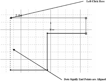
Figure 6
Move the cursor back to the original starting end point and left click once as shown...