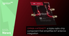
A two-dimensional, North-referenced coordinate System [73] is the principal coordinate System used throughout this book. Figure 3.1 shows the coordinate System and parameters defining bistatic radar operation in the plane containing the transmitter (T x), receiver (R x), and target (Tgt). It is called the bistatic plane [74]. The bistatic triangle lies in the bistatic plane. The distance L between the transmitter and receiver is called the baseline range, or simply baseline. The extended baseline is defined as continuing the baseline beyond either the transmitter or the receiver. The angles ? T and ? R are, respectively, the transmitter and receiver look angles, which are taken as positive when measured clockwise from North. They are also called angles of arrivai (AOA) or lines of sight (LOS). The bistatic angle ? is the angle between the transmitter and receiver with the vertex at the target. Note that ? = ? T- ? R. It is convenient to use ? in calculations of target-related parameters, and ? T or ? R in calculations of transmitter- or receiver-related parameters.
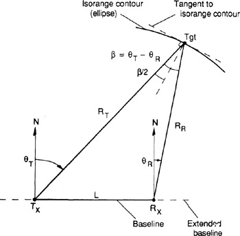 Figure 3.1: Bistatic radar North-referenced coordinate System in two dimensions
 When the target lies above the baseline (and extended baseline), such that ?90 < ? T < + 90 and ?90 < ? R < +90 , it is said to be in the "northern hemisphere." The "southern hemisphere" is similarly defined for targets lying below the baseline.
Copyright SciTech Publishing Inc. 2005 under license agreement with Books24x7