Digital Signal Processing Using MATLAB and Wavelets

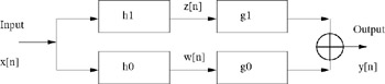
To demonstrate a general transform, we use Figure 9.3 below. Here, an input signal feeds to two channels, each with a pair of FIR filters. We call this structure a two-channel filter bank.
The left half of Figure 9.3 performs the forward transform, also called analysis, while the right half corresponds to the inverse transform, also called synthesis. When we talk about a transform such as the Haar transform or the wavelet transform, we refer only to the analysis part, the left half of the figure. On the other hand, the inverse Haar transform takes place on the right half of the figure. Putting the forward and inverse transforms together, we expect that the output of the two-channel filter bank ( y[ n]) is exactly the same as the input ( x[ n]), with the possible exception of a time delay, such as y[ n] = x[ n ? k], where k = 1 for two coefficients.
The complementary filters of a filter bank divide the signal into subsignals of low-frequency components and one of high-frequency components. This approach is called subband coding.
For the inverse transform, each of the filters' outputs ( w[ n] and z[ n]) goes to another FIR filter, after which the two channels are recombined by addition to form y[ n]. The idea...