9.7 Wavelet Filter Design Filters with Four Coefficients
Here we will examine designing a general filter bank with four taps per filter, very similar to that in the last section. However, one difference is that we use the z-transform in this section, which actually makes the analysis a bit easier. Figure 9.21 shows what this would look like. We specify values a, b, c, d and d, c, b, a for coefficients in one channel, with the understanding that the coefficients for the other channel are a reversed and sign-changed version of these. That is, in the other channel we would have the coefficients d, ? c, b, ? a and ? a, b, ? c, d, respectively.
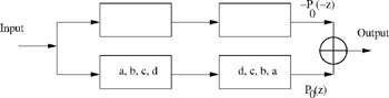 Figure 9.21: Designing a filter bank with four taps each.
 We will use H 0( z) and H 1( z) for the lowpass and highpass filters' transfer functions, respectively, while F 0( z) and F 1( z) are for the corresponding inverse filters. H 0( z) and F 0( z) go with the bottom channel in Figure 9.21.
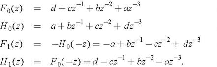
Examining the individual filter's responses, we see
Using P 0( z) and P 0( ? z) notation to represent the product of two sequential filters [3], for the top channel and the bottom channel, respectively, we get the following equations for a...