Wideband Amplifier Design

2.2: HIGH-FREQUENCY MODELS ([1] [4])

2.2 HIGH-FREQUENCY MODELS ([1] [4])

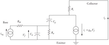
Figure 2-1 shows the commonly used linear, small-signal, hybrid- ?, bipolar-transistor model. It is valid for a circuit operating at a known DC operating point, and its validity extends from DC to high frequencies. Note that the base is separated from the internal base node by R bb. It works for most kinds of transistors since it includes just about all the stray elements that can exist. These elements are simply renamed for different kinds of devices (e.g., C jc for a bipolar device, and C gd for an FET device).


Figure 2-1: The hybrid- ? model frequently used in high-frequency analysis.

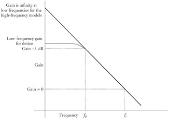
Figure 2-2 shows the gain with respect to frequency plot for this circuit. Note that it has a gain limit at low frequencies, and the point at which the gain begins to roll off is called f ?. The high-frequency models will decrease f ? to zero making the gain go to infinity at DC. While this assumption is not valid for low frequencies, it makes no difference for high frequencies and it makes the algebra far easier. Finally, f t is the point at which the device exhibits unity gain (a gain of 1) when loaded appropriately.


Figure 2-2: Gain with respect to frequency plot for the hybrid- ? model.

The hybrid- ? model and, by extension, the high-frequency models being developed depend on nonlinear parameters developed from basic device physics for...

UNLIMITED FREE
ACCESS
TO THE WORLD'S BEST IDEAS

SUBMIT
Already a GlobalSpec user? Log in.

This is embarrasing...

An error occurred while processing the form. Please try again in a few minutes.

Customize Your GlobalSpec Experience

Category: IC Electronic Filters
Finish!
Privacy Policy

This is embarrasing...

An error occurred while processing the form. Please try again in a few minutes.