Wideband Amplifier Design

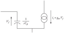
The first high-frequency model we will use is shown in Figure 2-3. Note that it has a single capacitor from base to emitter that creates the frequency dependence. If a current were driven into the input node of this device, then it would have infinite current gain at DC. At frequency f t, the gain would be 1. This is in keeping with the diagram in Figure 2-2. The question becomes how to determine the value for C ? and g m from the original device (or its hybrid- ? equivalent).
Some might suppose that this model is more appropriate for an FET device than for a BJT Some think that FETs are voltage-controlled devices, while BJTs are current-controlled ones making our model work for an FET but not a BJT. They would be wrong. This model is equally good for either. In any case, the assumption about BJTs being current controlled is incorrect. A BJT is a voltage-controlled device; it just has a lot more base current flowing at low frequencies and/or has a much lower DC input resistance than an FET. At high frequencies, all transistors tend to have low input impedance because of the input capacitance.
If we take the model shown in Figure 2-3 and drive the input with a voltage source while shorting the output to ground, then we can determine the ratio of i c/i b.